2. IPU-M2000 BMC specification
The IPU-M2000 baseboard management controller (BMC) runs software based on the OpenBMC project.
The responsibilities of the BMC software stack are to control, monitor and manage system hardware, including power, sensors, inventories and event logging.
You can control and monitor the system, via the BMC, using a variety of user interfaces such as a command line interface (CLI), graphical user interface (GUI), REST API, IPMI and Redfish.
2.1. BMC subsystem
A block diagram of the IPU-M2000, showing the BMC subsystem, is shown in Fig. 2.1.
The physical components in the BMC subsystem are:
ASPEED AST2520 baseboard management controller
System FPGA
128 MB serial boot flash
1 GB of DDR4 DRAM
One USB port — Micro-USB management interface, see Fig. 13.1
Two 1 GbE ports — at boot the BMC Ethernet interface (eth0) is set to 100 Mbps, full-duplex, auto-negotiation on
Two I2C PSU interfaces for monitoring the state of the power supplies
Five fan interfaces for controlling and measuring the speed of the system cooling fans
Three LEDs used to indicate status
2.1.1. System FPGA
The FPGA is mainly a status and control signal concentrator. It ensures that those control signals are always in a safe state. In addition, it provides hardware monitoring and protection for any thermal or voltage abnormalities. It also controls the sequencing of supply voltages, clocks and reset signals.
2.1.2. LEDs
There are three LEDs used to indicate status:
Green indicates normal operation status
White is used to identify a specific IPU-M2000 in a system
Yellow indicates various error conditions:
Temperature alert detected
Standby voltages detected failing
PSUs detected failing
Connector domain detected failing
GW 1 domain detected failing
IPU 1 and 2 or IPU 3 and 4 domains detected failing
Fan fail detected (too few fans or fans running too slow)
No profile configuration found in flash
BMC flash not trusted
2.2. BMC functions
The BMC supports the following system management functions:
2.3. IPU-M2000 block diagram
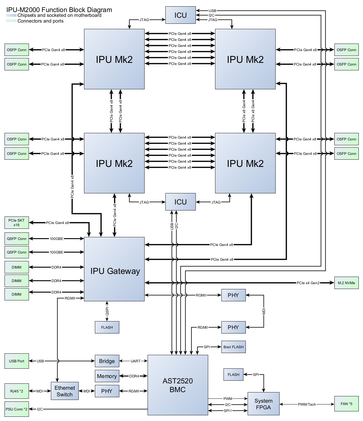
Fig. 2.1 IPU-M2000 BMC block diagram
2.4. Supported IPMI commands
2.5. Supported ipmitool commands
This section summarises the ipmitool commands supported by the BMC. For details of the
parameters and examples of use, see the appropriate user guide chapter.
The BMC is tested with ipmitool version 1.8.18.
Command |
Description |
|---|---|
fru print |
Display information about all FRUs |
fru print <fruid> |
Display information about the FRU with the specified ID |
Command |
Description |
|---|---|
sel clear |
Clear all event logs |
sel list |
Display list of events |
sel elist |
Display list of events with extended information |
Command |
Description |
|---|---|
lan print |
Print network information |
ipsrc dhcp |
Enable DHCP |
ipsrc static |
Configure static IP |
ipaddr <ip_address> |
Set IP address |
netmask <x.x.x.x> |
Set IP address |
defgw ipaddr <ip_address> |
Set default gateway IP address |
Command |
Description |
|---|---|
power off |
Hard power off |
power soft |
Soft power off |
power reset |
Warm reboot |
power on |
Power on |
bmc reset cold |
BMC reboot |
dcmi power get_limit |
Get current status of power cap |
dcmi power set_limit limit <limit> |
Set new power cap value |
dcmi power activate |
Enable power capping |
dcmi power deactivate |
Disable power capping |
Command |
Description |
|---|---|
sdr list |
Display sensor data repository (SDR) entry readings and their status |
sdr elist |
Display extended sensor information |
sensor list |
Display sensors and thresholds in a wide table format |
sdr get <sensor_name> |
Display information for sensor data records specified by sensor ID |
sdr type |
Display a list of sensor types |
sdr type <sensor_type> |
Display all records from the SDR repository of a specific type |
Command |
Description |
|---|---|
sol activate |
Access serial over LAN (SoL) interface |
Command |
Description |
|---|---|
sel time set “DD/MM/YYYY HH:MM:SS” |
Set time and date (will fail if system is in NTP mode) |
sel time get |
Get time and date |
Command |
Description |
|---|---|
user summary [<channel_number>] |
Print a summary, including number of users on the system |
user list [<channel_number>] |
List users |
user set name <user_id> <username> |
Create a user with <user_id> and <username> |
user set password <user_id> [<password> <16|20>] |
Create a password for user with <user_id> (the password can be 16 or 20 bytes in length) |
user enable <user_id> |
Enable user with <user_id> (must be done after creating user and password) |
user disable <user_id> |
Disable user with <user_id> |
user priv <user_id> <privilege_level> [<channel_number>] |
Set privilege level for user with <user_id> |
channel setaccess <channel> <user_id> ipmi=on |
Enable IPMI access for a user |
The maximum number of system users is 30
The maximum number of users with IPMI access is 15
The maximum username length for an IPMI user is 16 bytes
User IDs are from 1 to 15
Passwords must be a minimum of 8 characters in length
The privilege levels are:
0x1: Callback
0x2: User
0x3: Operator
0x4: Administrator
0x5: OEM Proprietary
0xF: No Access