21. C2 PCIe Device IDs and channel map
The following information applies to C2 cards in a PCIe server. For IPU-Machine and IPU-POD systems, see the appropriate product documentation.
21.1. Device IDs
The diagram below shows how single IPUs and then, hierarchically, groups of IPUs are numbered in a 16-IPU system. For example, device ID 25 corresponds to the four IPUs numbered 0 to 3. These numbers are the IDs used by tools such as gc-info.
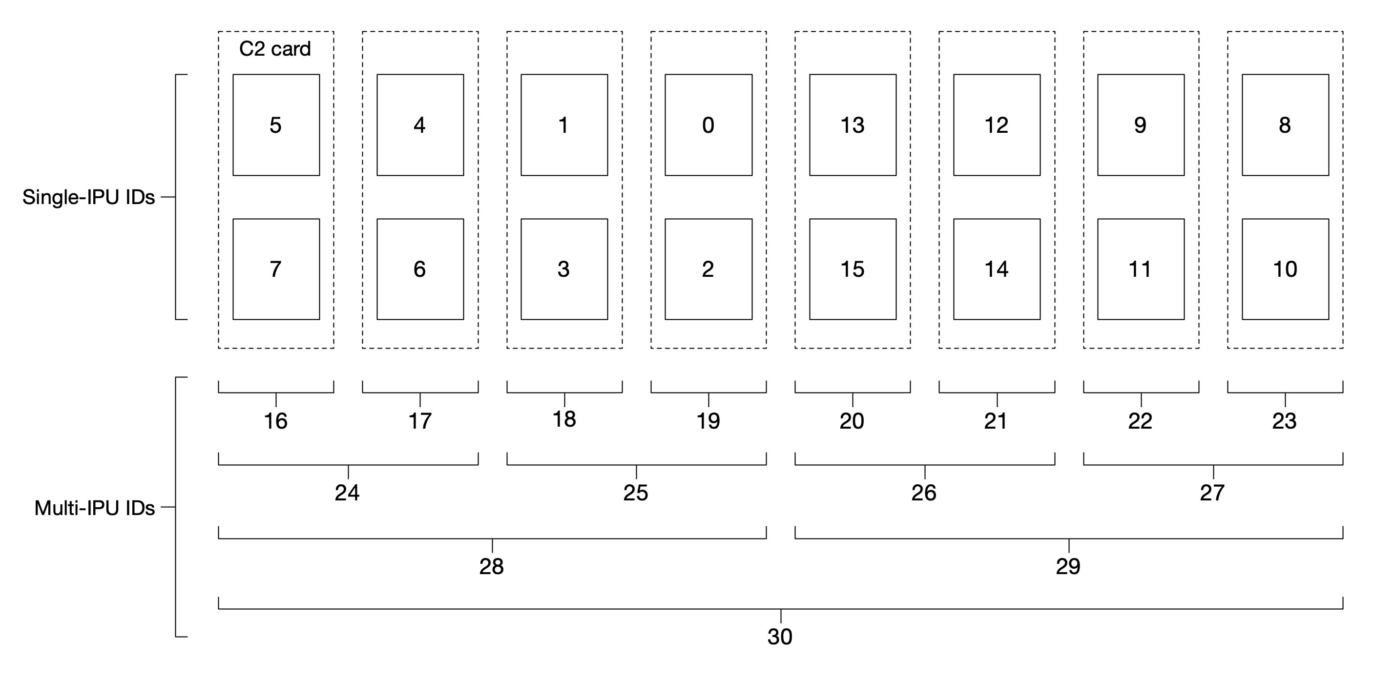
Fig. 21.1 IPU device IDs
21.2. IPU-Link channel mapping
The diagram below shows the how channels connect between the cards in a system.
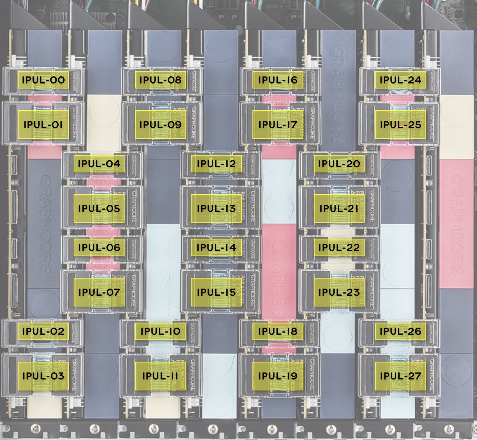
Fig. 21.2 IPU-Link card-to-card channel map
21.3. PCIe ID to slot mapping
The Graphcore tools typically deduce which IPU cards are in which PCIe slot via a table in the SMBIOS. Alternatively, a JSON configuration file may be provided by setting the environment variable GCDA_CONFIG_FILE. The file must have the following format:
{
  "ipu_card_mapping": [
   "0000:0f:00.0",
   "0000:0e:00.0",
   "0000:0d:00.0",
   "0000:0c:00.0",
   "0000:0b:00.0",
   "0000:0a:00.0",
   "0000:09:00.0",
   "0000:08:00.0",
   "0000:07:00.0",
   "0000:06:00.0",
   "0000:05:00.0",
   "0000:04:00.0",
   "0000:03:00.0",
   "0000:02:00.0",
   "0000:01:00.0",
   "0000:00:00.0"
  ]
}
Where “ipu_card_mapping” is an ordered list of the PCIe IDs for the Graphcore cards, from one side of the chassis to the next. Each pair of IDs should match a single card, and the next pair should be in the next physical slot.