7. IPU-POD128 installation
An IPU‑POD128 system consists of two IPU‑POD64 logical racks with GW-Link cables connected between them via a GW-Link switch. Table 7.1 shows the BOM for an IPU‑POD128, giving you options for either electrical (copper) or optical Ethernet cables for the GW-Links, depending on your datacentre layout - copper cables are suitable for racks that are adjacent, and optical cables for racks that are further apart.
Item |
Product number |
Description |
Quantity |
1 |
900-0020 |
IPU-POD64 Logical Rack |
2 |
2 |
Arista DCS-7060PX4-32-F |
GW-Link Switch |
1 |
3 |
Spline switch |
1 |
|
4 |
MCP1600-C01AE30N |
1.5m Direct Attach Ethernet 100GbE QSFP28 Passive Copper Cable for GW-Link (not needed if [5] & [6] are used) |
32 |
5 |
SM-ULC-DX-PVC-1.5M |
1.5m LC UPC to LC UPC Duplex OS2 Optical Cable for GW-Link (not needed if [4] is used) |
32 |
6 |
TR-ZC13H-N00 |
100Gb/s QSFP28 DR Single Lambda Optical Transceiver for GW-Link (not needed if [4] is used) |
64 |
7 |
CT8R02R-CDC25-DF |
1.5m Cat5e Ethernet Cable for 10GbE Switch Redundancy |
2 |
Fig. 7.1 shows the IPU‑POD128 layout and switched GW-Link cables between the two IPU‑POD64 racks.
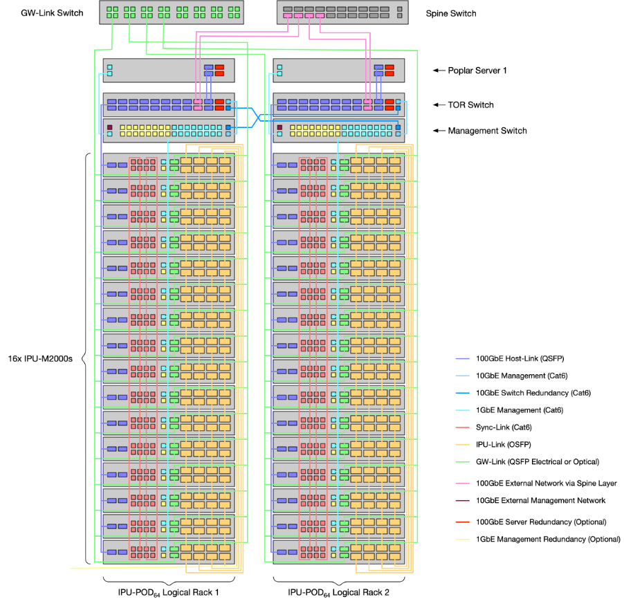
Fig. 7.1 IPU‑POD128 topology with switched GW-links
Fig. 7.2 shows the location of the GW-Link ports on the front of each IPU-M2000.
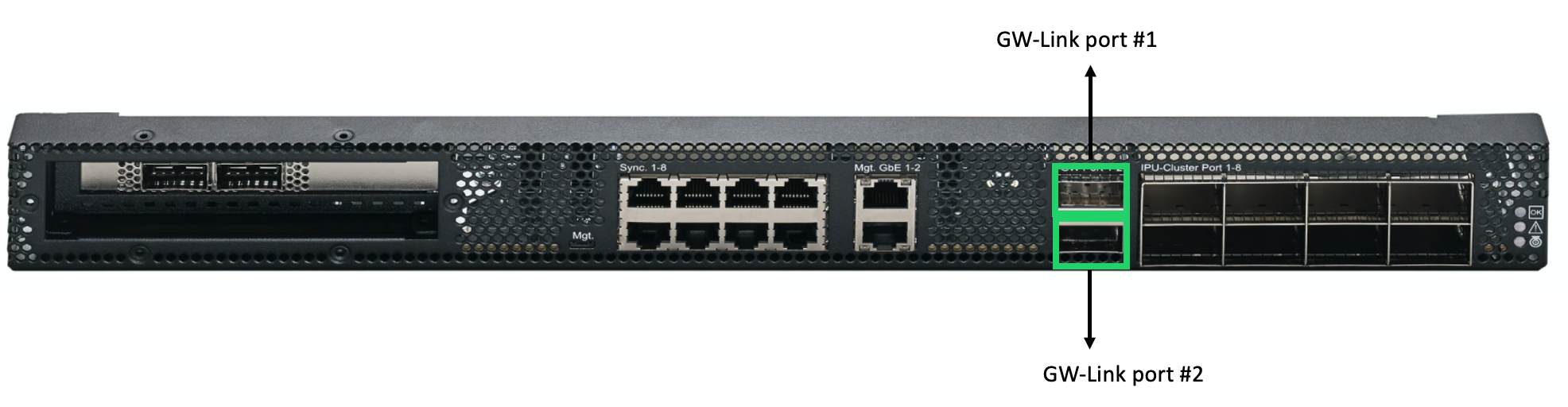
Fig. 7.2 IPU-M2000 front panel showing GW-Link ports