2. Product description
2.1. IPU‑POD128 system
Graphcore’s IPU‑POD128 system is built from two IPU‑POD64 logical racks, assembling 32 IPU-M2000 IPU-Machines together delivering nearly 32 petaFLOPS of AI compute. IPU‑POD64 logical racks can be used individually (64 GC200 IPU processors) or as building blocks for larger systems such as the IPU‑POD256 (256 GC200 IPUs), going up to 1024 IPU‑POD64 racks (64K GC200 IPU processors) delivering nearly 16 exaFLOPS of AI compute.
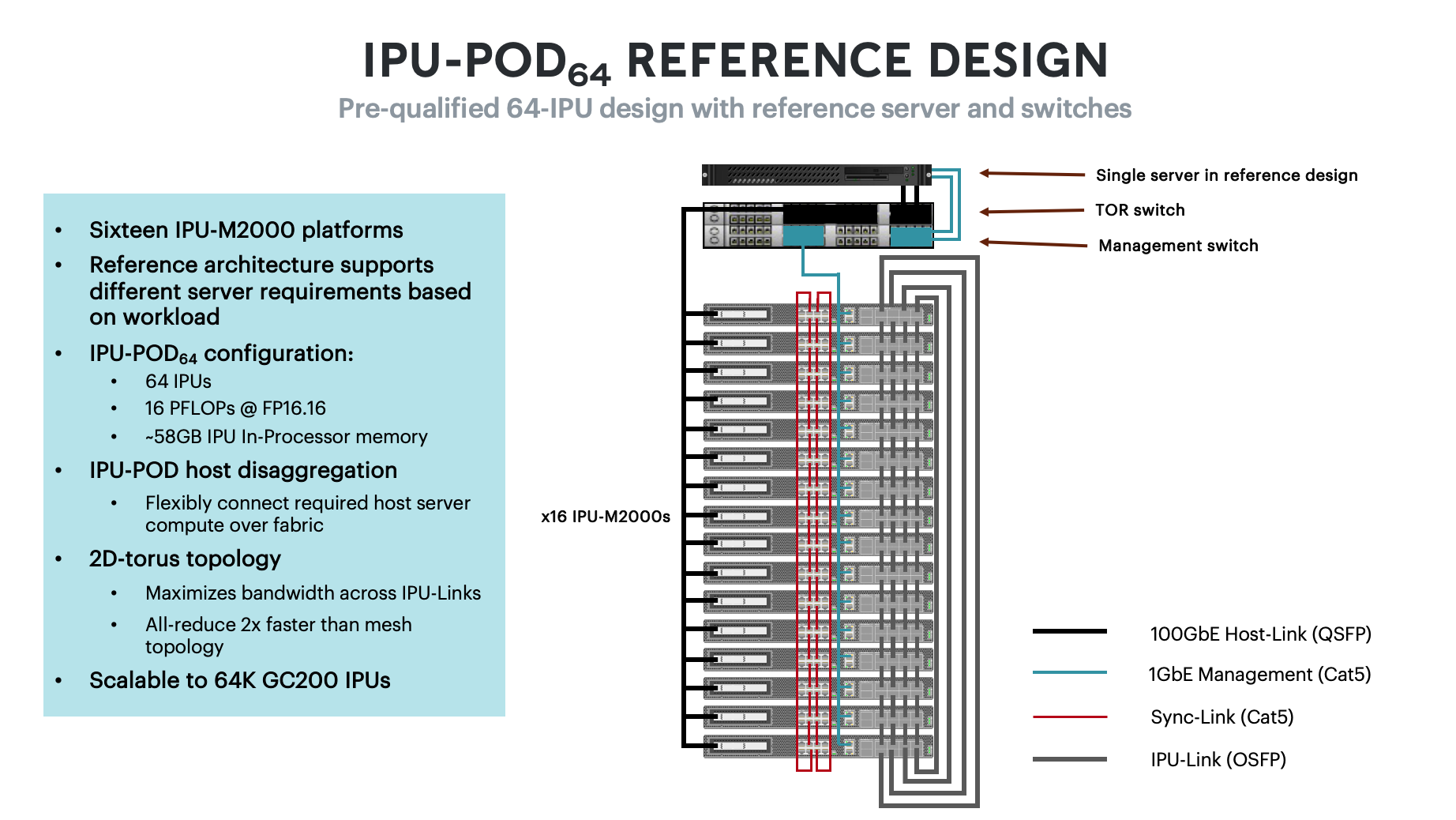
Each IPU‑POD64 in the system combines the sixteen IPU-M2000 IPU-Machines with network switches and a host server in a pre-qualified rack configuration (switches and host server not provided by Graphcore). The pre-qualified IPU‑POD64 system assumes the following default components:
1-4 approved host servers, see the approved server list for more details. In this datasheet we use the Dell R6525 server with dual-socket AMD Epyc2 CPUs as the default offering. Default number of servers is 1, however up to 4 host servers may be required depending on workload - please speak to Graphcore sales.
1 Arista 7060X ToR switch (32x100G + 2 10G)
1 Arista 7010T management switch (48p 1G+ 4x1/10G)
The IPU‑POD128 is characterized by the following features:
Disaggregated host architecture allows for different server requirements based on workload
31.955 petaFLOPS (FP16.16) of AI compute, 7.989 petaFLOPS @ FP32, and up to 8.4 TBytes of system memory
2D-torus IPU-Link topology
Scalable to 1,024 IPU‑POD64 racks supporting 65,536 GC200 IPU processors
A high-level view of the cabling for an IPU‑POD64 is shown in Fig. 2.1.

Fig. 2.1 IPU‑POD64 reference design rack
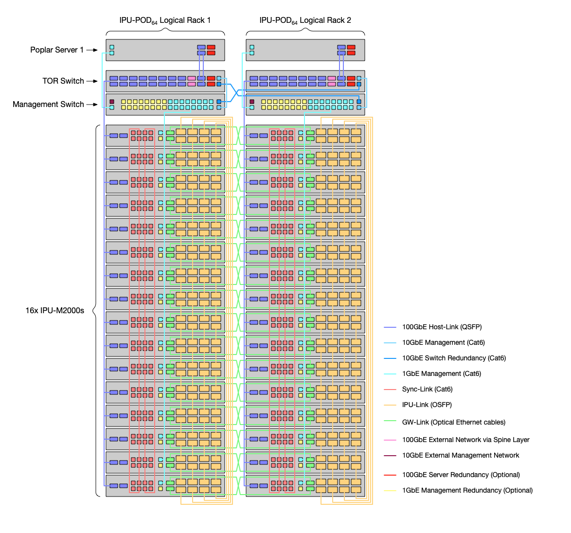
An IPU‑POD128 system consists of two IPU‑POD64 logical racks with optical GW-Link cables cross connected between them. Fig. 2.2 shows the IPU‑POD128 layout and cross connected GW-Link cables between the two IPU‑POD64 logical racks.

Fig. 2.2 IPU‑POD128 cabling
A logical rack is a space in a physical rack occupied by an IPU-POD - since an IPU‑POD64 only occupies half of a physical rack there can be two logical racks in one physical rack for an IPU‑POD128.
The IPU‑POD128 system is available as a full implementation through Graphcore’s network of reseller and OEM partners.
Alternatively, customers may directly implement an IPU‑POD128 system with the help of the IPU‑POD128 build and test guide.
2.2. Communication for scale-out: 3D IPU-Fabric with GCL
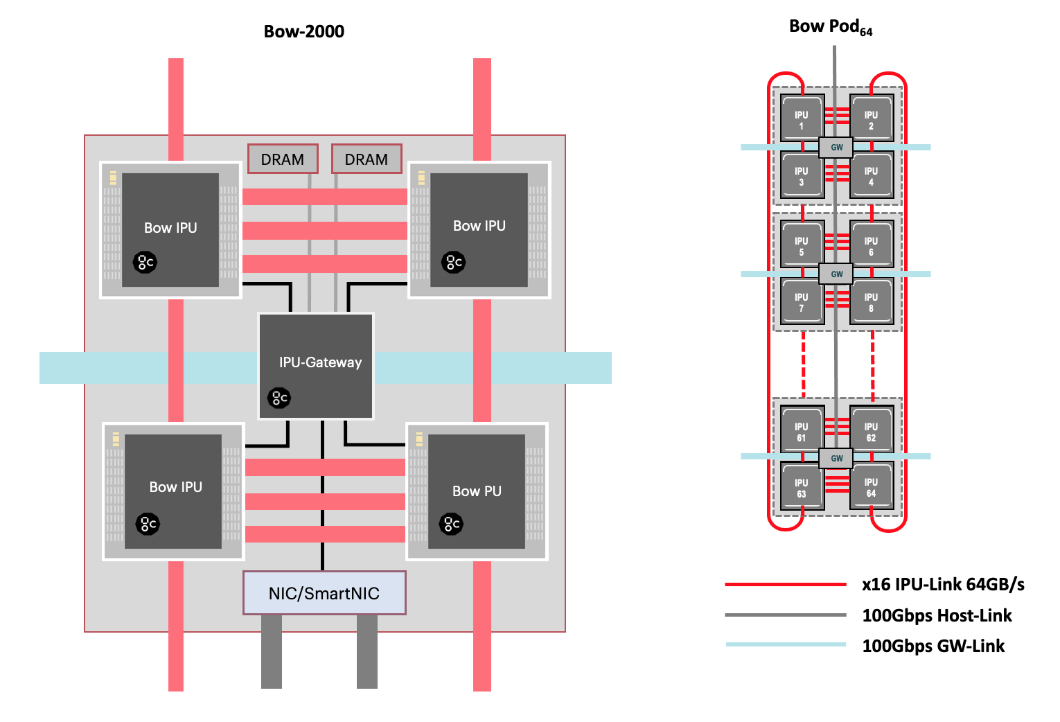
IPU‑POD128 systems build on the innovative IPU-Fabric, designed to support massive scale out. Fig. 2.3 below shows, on the left, an abstracted view of an IPU-M2000 with the IPU-Fabric interconnects comprising IPU-Links™, GW-Links (for jitter-free IPU-to-IPU connectivity), and the Host-Link 100Gbps RDMA connection between the host server and each IPU-M2000. The small insert on the right shows how these interconnects are used as part of IPU‑POD64 scale-out: IPU-Links join IPU processors together both within IPU-M2000s as well as between them; GW-Links connect between the IPU-Gateway chips in each IPU-M2000. The IPU-Link connections in each IPU‑POD64 of the IPU‑POD128 form a 2D torus since the loops are closed top and bottom.
The Graphcore Communication Library (GCL) manages the communication and synchronization between IPUs across any IPU-Fabric, supporting ML at scale.

Fig. 2.3 IPU-Fabric
2.3. Host-Links and GW-Links
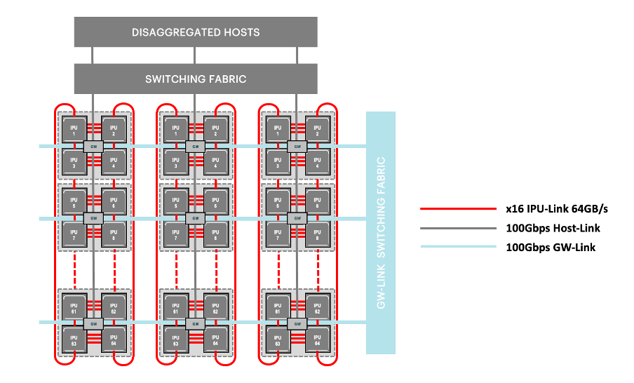
Host servers are disaggregated from the IPU-M2000s with Host-Links – Graphcore´s low-latency high throughout host-IPU RDMA transport using RoCEv2. The 100Gbps Ethernet links from the RoCEv2 NICs in the IPU-M2000s connect through switches to the disaggregated host servers. This disaggregated host architecture for the IPU‑POD64 enables user-defined host:IPU ratios and allows for scalable host server utilisation depending on the machine intelligence workload. The GW-Links are used to connect multiple IPU‑POD64 logical racks either directly or through an optional Ethernet switching fabric as shown in Fig. 2.4.

Fig. 2.4 Host-Links and GW-Links
2.4. Software
IPU-POD systems are fully supported by Graphcore’s Poplar® software development environment, providing a complete and mature platform for ML development and deployment. Standard ML frameworks including TensorFlow, Keras, ONNX, Halo, PaddlePaddle, HuggingFace, PyTorch and PyTorch Lightning are fully supported along with access to PopLibs through our Poplar C++ API. Note that PopLibs, PopART and TensorFlow are available as open source in the Graphcore GitHub repo https://github.com/graphcore. PopTorch provides a simple wrapper around PyTorch programs to enable the programs to run seamlessly on IPUs. The Poplar SDK also includes the PopVision™ visualisation and analysis tools which provide performance monitoring for IPUs - the graphical analysis enables detailed inspection of all processing activities.
In addition to these Poplar development tools, the IPU‑POD128 is enabled with software support for industry standard converged infrastructure management tools including OpenBMC, Redfish, Docker containers, and orchestration with Slurm and Kubernetes.

Fig. 2.5 IPU-POD software
Complete end-to-end software stack for developing, deploying and monitoring AI model training jobs as well as inference applications on the Graphcore IPU |
|
|---|---|
ML frameworks |
TensorFlow, Keras, PyTorch, Pytorch Lightning, HuggingFace, PaddlePaddle, Halo, and ONNX |
Deployment options |
Bare metal (Linux), VM (HyperV), containers (Docker) |
Host-Links |
RDMA based disaggregation between a host and IPU over 100Gbps RoCEv2 NIC, using the IPU over Fabric (IPUoF) protocol |
Host-to-IPU ratios supported: 1:16 up to 1:64 |
|
Graphcore Communication Library (GCL) |
IPU-optimized communication and collective library integrated with the Poplar SDK stack |
Support all-reduce (sum,max), all-gather, reduce, broadcast |
|
Scale at near linear performance to 64k IPUs |
|
PopVision |
Visualization and analysis tools |
To see a full list of supported OS, VM and container options go to the Graphcore support portal https://www.graphcore.ai/support
IPU-Fabric topology discovery and validation |
|
|---|---|
Provisioning |
gRPC and SSH/CLI for IPU allocation/de-allocation into isolated domains (vPods) |
Plug-ins for SLURM and Kubernetes (K8) |
|
Resource monitoring |
gRPC and SSH/CLI for accessing the IPU-M2000 monitoring service |
Prometheus node exporter and Grafana (visualization) support |
|
Baseboard Management Controller (OpenBMC) |
Dual-image firmware with local rollback support |
Console support, CLI/SSH based |
Serial-over-Lan and Redfish REST API |
2.5. Technical specifications
IPU-Machines |
32x IPU-M2000 blades |
IPUs |
128 GC200 IPU processors (4 in each IPU-M2000) |
IPU-Cores™ |
188,416 |
Worker threads |
1.13 million |
AI compute |
31.955 petaFLOPS AI (FP16.16) compute |
7.998 petaFLOPS FP32 compute |
|
Memory |
Up to 4,211.2 GB (includes 115.2 GB In-Processor-Memory (32x 3.6GB per IPU-M2000) and 4096 GB Streaming Memory (32x 64 GB DIMM x2 per IPU-M2000) |
IPU‑POD128 host server(s) |
Default: 1 x Dell PowerEdge R6525 server per IPU‑POD64 |
Options: 1 – 4 Graphcore approved servers per IPU‑POD64. Contact Graphcore sales for details |
|
IPU‑POD128 default switches |
1 x Arista DCS-7060CX-32S-F (100GbE ToR switch) per IPU‑POD64 |
1 x Arista DCS-7010T-48-F (1GbE Management switch) per IPU‑POD64 |
IPU-Links |
64 Tbps (128 x16 Gen4) aggregated bi-directional bandwidth for direct, 2D torus intra-rack IPU‑POD128 IPU connectivity |
32 IPU-M2000s directly connected |
|
256 standard OSFP ports with DAC cabling |
|
GW-Links |
12.8 TBps (64 x 100Gbps) for inter-rack IPU‑POD64 connectivity |
Up to 1024 IPU‑POD64 (direct) or 256 IPU‑POD64 (switched) can be connected |
|
Standard 100Gbps QSFP28 ports supporting industry standard transceivers (100G-DR) and DAC cabling |
IPU‑POD64 server(s) to IPU-M2000 connectivity |
1 (default) to 4 host servers have connectivity to the 16 IPU-M2000s via the IPU‑POD64 100GbE ToR switch (Arista DCS-7060CX-32S-F) |
1x 100GbE port per IPU-M2000 to connect to the ToR switch |
|
Dual (2x) 100GbE ports per host server to connect to the ToR switch |
|
IPU‑POD64 internal management network connectivity |
Aggregated in the Arista DCS-7010T-48-F 1GbE management switch are: |
2x 1GbE RJ45 management ports from each of the IPU-M2000s |
|
Server management port(s) |
|
PDU monitoring port |
Air cooled |
Built-in N+1 hot-plug fan cooling system in each of the individual components (IPU-M2000s, servers and switches) |
Rack airflow |
All IPU‑POD64 components (IPU-M2000s, server(s) and switches) are mounted for airflow direction front of rack (single door, cold aisle side) to back of rack (split door, hot aisle side) |
Airflow rate |
103 CFM (measured) per IPU-M2000 (1648 CFM total in IPU‑POD64) |
Rack |
42U - 600mm (W) X 1200mm (D) x 1991mm (H) |
Weight |
450 kg (943 lbs) |
PDU |
PDU implementation can be customized for target workload and rack power density goals. Please contact Graphcore sales for any help required specifying the PDU implementation |
Input power (Vac) |
100 - 240 Vac (115 - 230 Vac nominal) |
Power cap |
1500 W with programmable power cap |
Redundancy |
1+1 redundancy |
Power (nominal) |
19 kW |
For information on IPU‑POD128 integration with datacentre infrastructure, please contact Graphcore sales.
2.6. Environmental characteristics
Operating temperature and humidity (inlet air) |
10-32C (50 to 90F) at 20%-80% RH (*) |
Operating altitude |
0 to 3,048m (0-10,000ft) (**) |
(*) Altitude less than 900m/3000ft and non-condensing environment
(**) Max. ambient temperature is de-rated by 1°C per 300m above 900m
For power caps higher than 1700W per IPU-M2000 please contact Graphcore sales for environmental guidance.
2.7. Standards compliance for IPU-M2000 IPU-Machines
EMC standards |
Emissions: FCC CFR 47, ICES-003, EN55032, EN61000-3-2, EN61000-3-3, VCCI 32-1 |
Immunity: EN55035, EN61000-4-2, EN61000-4-3, EN61000-4-4, EN61000-4-5, EN61000-4-6, EN61000-4-8, EN61000-4-11 |
|
Safety standards |
IEC62368-1 2nd Edition, IEC60950-1, UL62368-1 2nd Edition |
Certifications |
North America (FCC, UL), Europe (CE), UK (UKCA), Australia (RCM), Taiwan (BSMI), Japan (VCCI) |
South Korea (KC), China (CQC) |
|
CB-62368, CB-60950 |
|
Environmental standards |
EU 2011/65/EU RoHS Directive, XVII REACH 1907/2006, 2012/19/EU WEEE Directive |
The European Directive 2012/19/EU on Waste Electrical and Electronic Equipment (WEEE) states that these appliances should not be disposed of as part of the routine solid urban waste cycle, but collected separately in order to optimise the recovery and recycling flow of the materials they contain, while also preventing potential damage to human health and the environment arising from the presence of potentially hazardous substances.
The crossed-out bin symbol is printed on all products as a reminder, and must not be disposed of with your other household waste.
Owners of electrical and electronic equipment (EEE) should contact their local government agencies to identify local WEEE collection and treatment systems for the environmental recycling and /or disposal of their end of life computer products. For more information on proper disposal of these devices, refer to the public utility service.

2.8. Ordering information
IPU-POD systems are available to order from Graphcore channel partners – see https://www.graphcore.ai/partners for details of your nearest Graphcore partner.