1. Switched GW-Links in large scale Bow Pod systems
GW-Links provide IPU-to-IPU connectivity through the IPU-Gateway chip on each IPU-Machine, either via a directly connected link or via a switching infrastructure.
1.1. Bow-2000 links
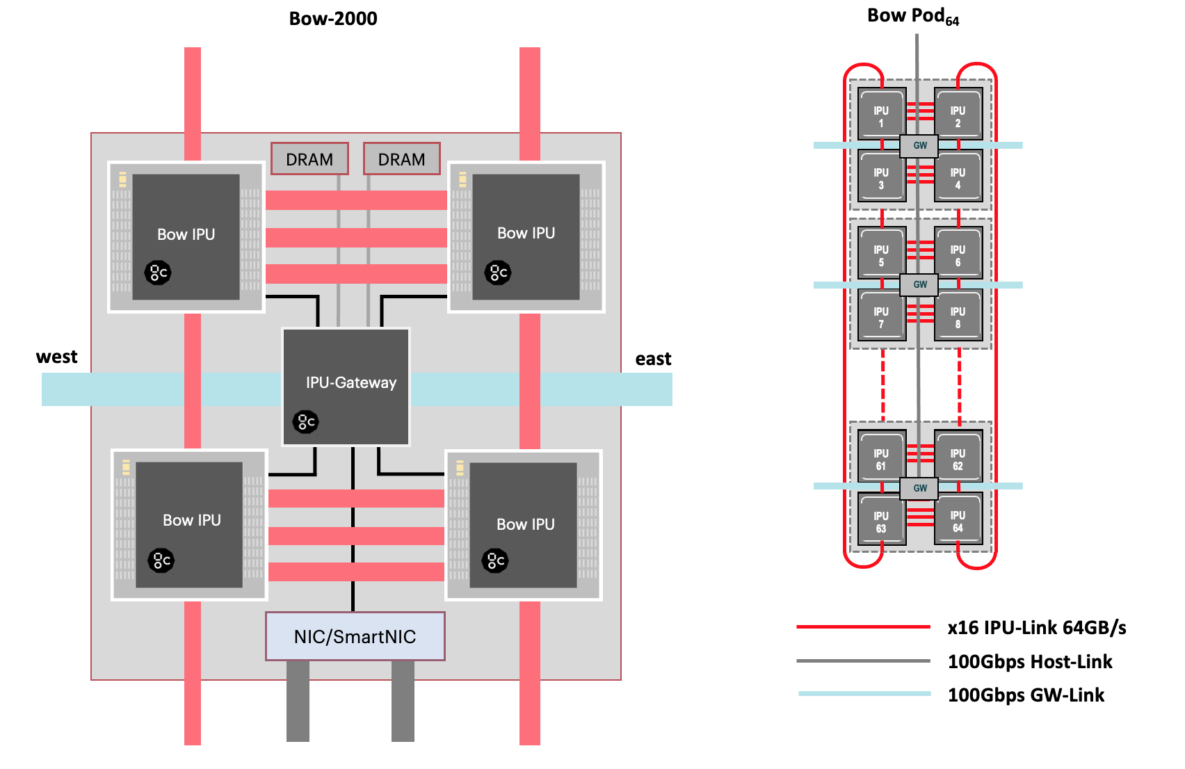
The diagram below shows the IPU-Link and GW-Link connections on a Bow-2000 IPU-Machine and a Bow Pod64.

Fig. 1.1 Bow-2000 IPU-Machine connections
1.2. Directly connected GW-Links
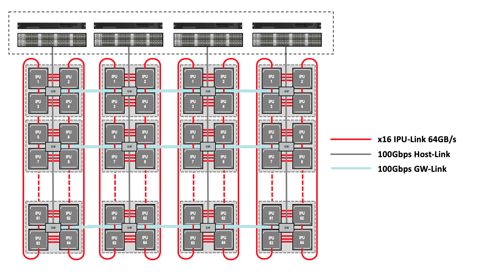
Fig. 1.2 shows the GW-Link cabling of a hypothetical Bow Pod256 system with directly connected GW-Links. This has four Bow Pod64 logical racks connected together with GW-Links. Each Bow-2000 has two GW-Link ports, named ‘east’ and ‘west’. This terminology is used to represent the connection direction: the GW-Link cable layout results in a horizontal (east-west) looped topology alongside the IPU-Links which form a loop in the vertical direction (north-south), and so the GW-Links and IPU-Links together form a 3D torus.

Fig. 1.2 Directly connected GW-Links in a Bow Pod256 (horizontal GW-Link loopback connections not shown)
For racks r0, r1, r2 and r3, the details of the cabling would be:
(*loops around to r3bow1* -- r0bow1 -- east)/(west -- r1bow1 -- east)/(west
-- r2bow1 -- east)/(west -- r3bow1 -- *loops around to r0bow1*)
(*loops around to r3bow0* -- r0bow0 -- east)/(west -- r1bow0 -- east)/(west
-- r2bow0 -- east)/(west -- r3bow0 -- *loops around to r0bow0*)
1.3. The benefits of using switched GW-Links
As Bow Pods expand to larger systems, using GW-Links to horizontally connect all of the Bow-2000s in each individual rack becomes complicated and prone to error. This brings an increased risk of downtime if an individual rack within the Bow Pod system needs to be taken out of service. A different approach is therefore required for large scale Bow Pod systems: the solution is to use switched GW-Links, where the GW-Link cables no longer connect directly between Bow-2000s, but instead indirectly pass through one or more switches (GW-Link switches) in between Bow Pod system components. With 100Gbps GW-Link interfaces and and switches, this configuration update has minimal impact upon bandwidth and latency.
1.4. Switched GW-Links
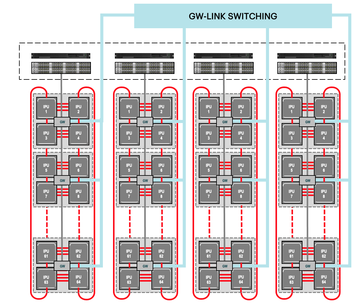
With switched GW-Links there are no direct GW-Link connections between the Bow-2000 IPU-Machines: the individual GW-Link cables from each Bow-2000 are connected to a switch (or multiple switches connected together for larger systems). MAC table entries must be auto-discovered or manually input on these switches to ensure that data is routed to the correct destination (see Section 1.4.2, Static MAC address learning). By using switches instead of direct connections, we can scale-up Bow Pod systems much more easily and reduce the overall number of hops required for data to traverse the system.

Fig. 1.3 Switched GW-Links in a Bow Pod256
Below is an example of how this could look for a Bow Pod256:
([00] -- r0bow1 -- [01])/([02] -- r1bow1 -- [03])/([04] -- r2bow1 -- [05])
/([06] -- r3bow1 -- [07])
([08] -- r0bow0 -- [09])/([10] -- r1bow0 -- [11])/([12] -- r2bow0 -- [13])
/([14] -- r3bow0 -- [15])
...
where [xx] denotes a switch port.
For Bow Pod256 systems consisting of four Bow Pod64 logical racks connected together, we will need 128 switch ports since there are two GW-Link ports per Bow-2000 IPU-Machine. Whilst this could possibly be implemented using a single switch, it is more likely that we would use multiple switches due to the increased cost and limited availability of managed switches that have such a large number of ports.
For very large Bow Pod1024 systems, a total of 512 switch ports are required for GW-Links alone, and so it is necessary to use multiple switches.
1.4.1. Network switch configuration for switched GW-Links
We recommend that the Ethernet switches used to handle GW-Link traffic are dedicated to this task. They should be isolated (except for a connection to a management network for configuration and monitoring) and should not be required to carry unrelated network traffic.
Switch ports connected to Bow-2000 GW-Link ports must allow access to, and tag all traffic with, VLAN 10.
Flow control should be enabled for Rx and Tx operations.
All ports must be set to trunk mode.
We recommend that you enable priority flow control and disable the dropping of any prioritised packet.
Only optical cables are supported for connection to GW-Link ports. All switch ports connected to Bow-2000 GW-Link ports must have FEC (forward error correction) disabled. This is necessary for performance reasons and to avoid a major source of latency.
1.4.2. Static MAC address learning
Since IPU-M software release 2.5.0, as long as the switch ports connected to GW-Link interfaces are configured to apply the correct VLAN tags (see above), then the switch will be able to auto-learn the connected MAC addresses automatically without manual input.
(In previous releases the Bow-2000 GW-Link hardware ran with a lightweight driver which required a static table of MAC addresses to be configured on the switch.)
1.5. Packetised sync
Bow Pod systems must internally propagate the necessary triggers for the system-wide synchronisation element of the BSP cycle. Between Bow-2000s within the same logical rack, this sync signal is transmitted through dedicated Sync-Link ports with short, directly connected Sync-Link cabling. For larger multi-rack Bow Pod systems, between-rack sync signals are carried via the GW-Link connections as standard Ethernet frames, which we refer to as “packetised sync”. Previously the Sync-Link ports used a bespoke protocol, but all Bow Pod sync signalling is now consistently packetised.
The Ethernet frames used for packetised sync over switched GW-Links can be tagged with a VLAN ID which means the Bow Pod system can be divided into a number of smaller isolated segments. For example, we could divide a 4-rack Bow Pod256 system into two logical Bow Pod128 partitions, each Bow Pod128 with its own distinct VLAN tag. In this way we could allow two different customers access to the Bow Pod256, each only able to use their specific Bow Pod128 with assured privacy of their workloads.
By contrast, with directly connected GW-Links, all parts of the system have to be on the same VLAN. This is much more restrictive since it means that we can’t allow different customers to use different parts of the Bow Pod system to run their workloads in isolation.