1. Overview
The Graphcore® C600 IPU-Processor card is a dual-slot, full-height PCI Express Gen4 card containing Graphcore’s Mk2 IPU with FP8 support, designed to accelerate machine intelligence applications for both training and inference. All other components are supplied by industry-standard vendors. GC-C600 is the regulatory model for the C600 PCIe card.
The C600 has a thermal design power (TDP) of 185 W running typical workloads and is passively cooled when installed in a suitable chassis enclosure. The maximum power of the card is capped and can be configured to be higher or lower, should that be required.
All the memory on the card is contained within the IPU, providing extremely high bandwidth to the processing cores. There is a total of 900 MB of In-Processor-Memory in the IPU.
1.1. Label information
This section describes the position and content of the labels on the C600.
Both C600 and IPU device identification can be obtained from the SMBus interface when the C600 card is powered; for more details see the C600 SMBus Interface specification.
1.1.1. Card label
On the top of the C600 (visible when the C600 card is installed) is a label that repeats the PCB card identification information for your C600 card.
The command line tool gc-inventory can also be used to find the PCB serial number of a C600 card.
1.1.2. PCB card label
On the bottom of the C600 card there is a small cutout in the metal cover which shows the PCB card identification label.
Note that this label is not visible when the card is installed in a chassis.
1.1.3. Tamper proof label
On the reverse side of the card there is a tamper proof label. The lid of the C600 SHOULD NOT BE REMOVED and this label will indicate if this has occurred.
Note that this label is not visible when the card is installed in a chassis.
1.2. Physical specifications
The C600 card conforms to the PCIe CEM specification for dual-slot, full-height Gen4 PCIe cards. An additional 2.5 mm clearance is required to allow for the IPU-Link™ card-to-card assembly for systems where cards need to be connected together. A mechanical model (STP file) can be provided on request from Graphcore support.
1.2.1. Dimensions
Card length |
267 mm |
Card height |
111 mm |
Assembly height |
113.5 mm to top of attached IPU-Link connector |
Assembly width |
27.6 mm |
Mass |
1.27 kg |
1.2.2. PCIe extender brackets
Depending on the chassis the cards will be installed in, there are different types of PCIe extender bracket available to ensure a secure fitting of the C600 into the PCIe slot. These brackets are described in Section 2.2, Extender brackets for C600 card support.
1.3. Power requirements
Power is supplied to the C600 card via a 3 V connection on the PCIe edge connector and a 12 V power supply (see Section 1.3.1, 12 V auxiliary power supply specification). The power socket is mounted on the edge of the PCB at the opposite end to the mounting bracket.
Connection |
Voltage |
Specified current |
Specified power |
Timescale |
PCIe edge connector |
12 V ± 8% |
0 A |
0 W |
N/A |
PCIe edge connector |
3V3 ± 9% |
1 A |
3.3 W |
20 ms |
CPU8 pin power connector (AUX) |
12 V +5% / -8% |
16 A |
192 W |
20 ms |
TDP |
185 W |
Power cap |
Adjustable in multiples of 12W depending on customer spec, typically 180 W or 192 W |
Power cap adjustment resolution |
12 W |
Power capping sample time |
1 ms |
Parameter |
Peak current |
Timescale |
PCIe edge connector (12 V) |
0 A |
N/A |
CPU8 pin power connector (AUX, 12 V) - default |
16 A** |
20 ms |
CPU8 pin power connector (AUX, 12 V) - absolute max |
21 A** |
20 ms |
CPU8 pin power connector (AUX, 12 V) |
30 A |
1 ms |
Note
** 20 ms averaged peak current depends upon the power cap value. For expected workloads this should be left at the default value. In cases where this is increased the chassis power capacity needs to be adjusted accordingly.
1.3.1. 12 V auxiliary power supply specification
An auxiliary power supply is required to provide the necessary power to the C600 card. Fig. 1.1 shows the pin-out diagram for the 8-pin C600 power socket.
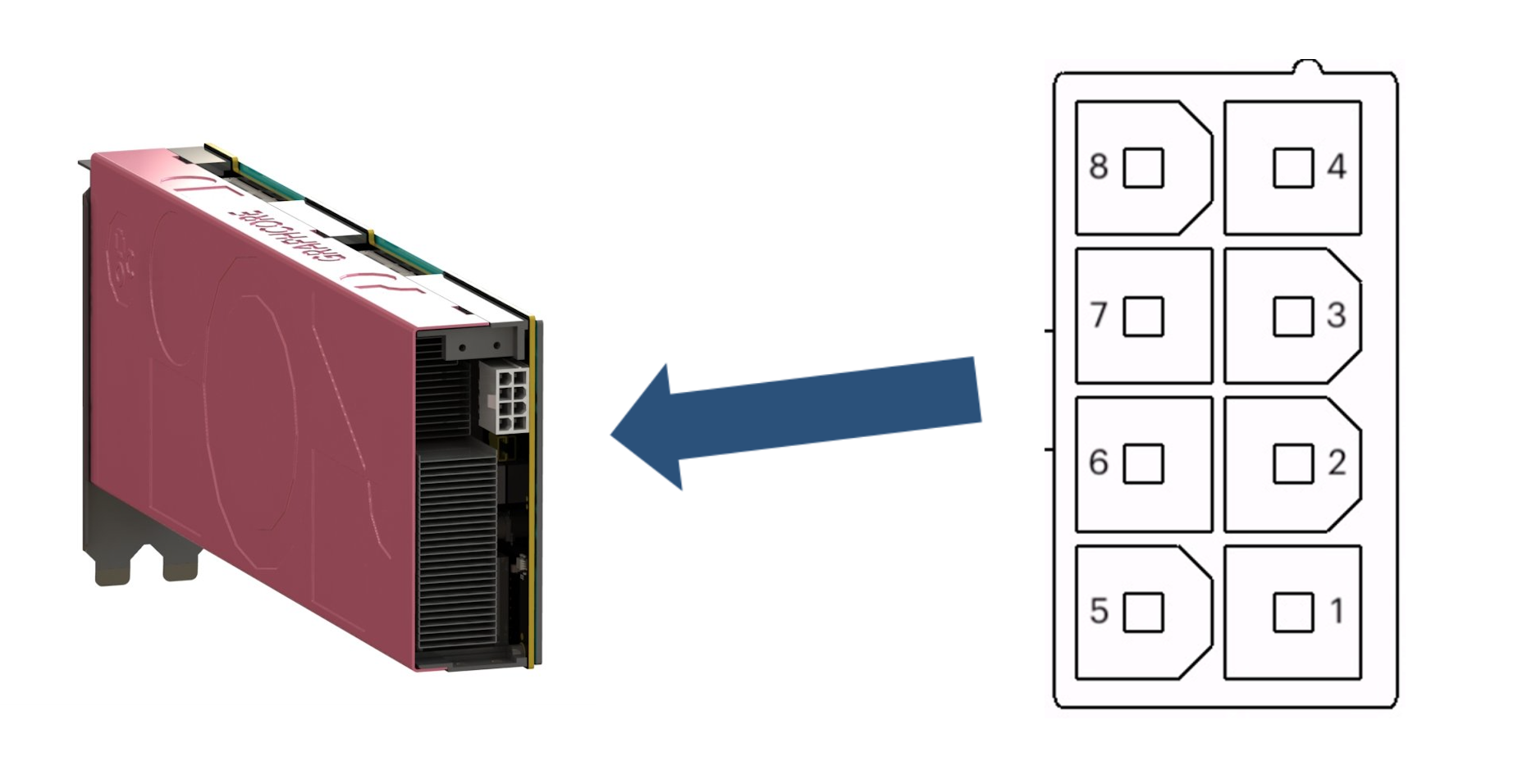
Fig. 1.1 C600 8-pin 12 V connector pinout
Table 1.5 shows the connection summary for the C600 power socket.
Pins 1 - 4 |
Ground |
Pins 5 - 8 |
12 V |
1.4. Thermal requirements
The C600 card is passively cooled when situated in a suitable chassis enclosure. Fans within the chassis housing the C600 card(s) need to deliver sufficient airflow to keep the cards below their maximum operational temperature threshold, removing 252 W of heat per C600 card to allow for the maximum value of power capping.
See Section 2.1, Airflow requirements for more details about airflow requirements.
1.4.1. Operating conditions
The C600 operates between 10°C (50°F) and 55°C (131°F) ambient temperature. The maximum external exhaust temperature is 70°C (158°F). Relative humidity should be kept between 5% and 90%. Power consumption is reduced if either the C600 component temperatures or the input currents exceed their maximum thresholds.
1.4.2. Storage conditions
The C600 can be safely stored between -40°C (-40°F) and 70°C (158°F). Relative humidity should be kept between 5% and 90%.
1.4.3. Temperature sensors
There are four temperature sensors on the C600 circuit board: one under the IPU device, one in the centre of the PCB and one at each end of the board, to measure inlet and outlet PCB temperature. These temperature readings are refreshed every 1 s.
The temperature readings are available on the SMBus, and through the PCIe bus for chassis fan control. See the SMBus Interface Specification document on http://smbus.org/specs/ for full details. They are also available through the PCIe bus for user visibility.
1.5. Compute
The IPU has 1,472 individual machine intelligence cores, generating up to 560 teraFLOPS of FP8 and 280 teraFLOPS of FP16 compute.
1.5.1. IPU control unit (ICU)
The ICU is powered from the 3.3 V PCIe supply. It is responsible for a number of actions on the C600 board including power sequencing, PCIe configuration, and thermal control. The ICU can communicate with the host machine via both the SMBus and the PCIe bus.
1.5.2. Cluster networking
The C600 card supports four IPU-Links with a total of 1 Tbps bi-directional bandwidth. C600 cards can be joined together into a cluster of up to eight C600 cards, with each pair of cards linked together with an IPU-Link cable carrying 2 IPU-Links. This gives a much higher IPU-IPU interconnect speed than is available through the PCIe bus alone. See Section 2.5, IPU-Link cables for more details.
1.5.3. Software support
The C600 card is programmed using the Poplar® SDK, Graphcore’s software stack for IPUs. This supports leading machine learning frameworks such as PyTorch, TensorFlow and ONNX and includes the Poplar graph programming framework which can be used to program the IPU directly using C++. Details about how to install the software required are given in Section 2.6, Installing host software.
1.6. LED indicators
The C600 card has six LED indicators which are visible through the front mounting bracket. These LEDs show diagnostic information about the current state of the card.
The IPU on the C600 has dual 8-lane Gen4 PCIe interfaces. The primary interface (primary complex) is on lanes [7:0] and the secondary interface (secondary complex) is on lanes [15:8].
LED #5 shows diagnostic information about the status of the primary PCIe interface and LED #6 shows diagnostic information about the status of the secondary PCIe interface. The primary and secondary PCIe interfaces are referred to as primary complex and secondary complex, respectively, in Table 1.6.
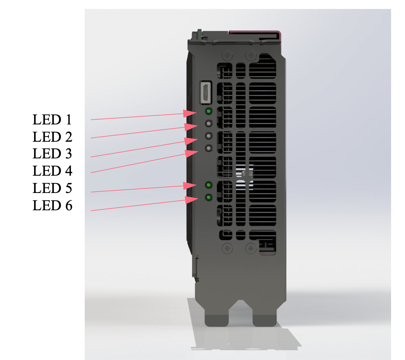
Fig. 1.2 C600 LED indicators
The diagnostic information available is given in Table 1.6.
LED |
Colour |
Function |
|---|---|---|
1 |
Green Red |
Power supplies operating normally Power supply failure detected |
2 |
None Red |
All sensors operational System has detected an issue with 1 or more system sensors |
3 |
None Red |
Temperatures normal Over-temperature condition |
4 |
None Red |
System functioning correctly Critical fault |
5 |
Green Red Blue |
Primary complex (PCIe [7:0]) links functioning correctly Primary complex (PCIe [7:0]) failed to establish link connectivity Link training in progress |
6 |
Green Red Blue |
Secondary complex (PCIe [15:8]) links functioning correctly Secondary complex (PCIe [15:8]) failed to establish link connectivity Link training in progress |
For any issues with your C600 card you can contact your Graphcore representative or Graphcore support.
1.6.1. Successful boot indication
During normal operation LED #1, LED #5, and LED #6 should be green.
All other LEDs should be off.
1.7. PCIe information
The PCIe information for C600 cards is given in Table 1.7.
Item |
Description |
|---|---|
Vendor ID |
0x1D95 |
Device ID |
0x0600 |
Sub-Vendor ID |
0x1D95 |
Sub-System ID |
0x0102 (primary interface) |
1.8. Software
C600 cards are fully supported by Graphcore’s Poplar® software development kit, a complete end-to-end software stack for developing, deploying and monitoring AI model training and inference on the Graphcore IPU. Standard ML frameworks including TensorFlow, Keras, ONNX, Halo, PaddlePaddle, Hugging Face, PyTorch and PyTorch Lightning are fully supported along with access to PopLibs through our Poplar C++ API. Note that PopLibs, PopTorch, PopART and the IPU-specific forks of TensorFlow and Keras are available as open source in the Graphcore GitHub organisation https://github.com/graphcore. PopTorch provides a simple wrapper around PyTorch programs to enable the programs to run seamlessly on IPUs. Developers can also use the PopVision™ visualisation and analysis tools to gain a deep understanding of IPU performance and utilisation - the graphical analysis enables detailed inspection of all processing activities.
In addition to Poplar and PopVision, C600 systems are enabled with software support for industry standard converged infrastructure management tools such as Docker containers, as well as orchestration with Slurm and Kubernetes.
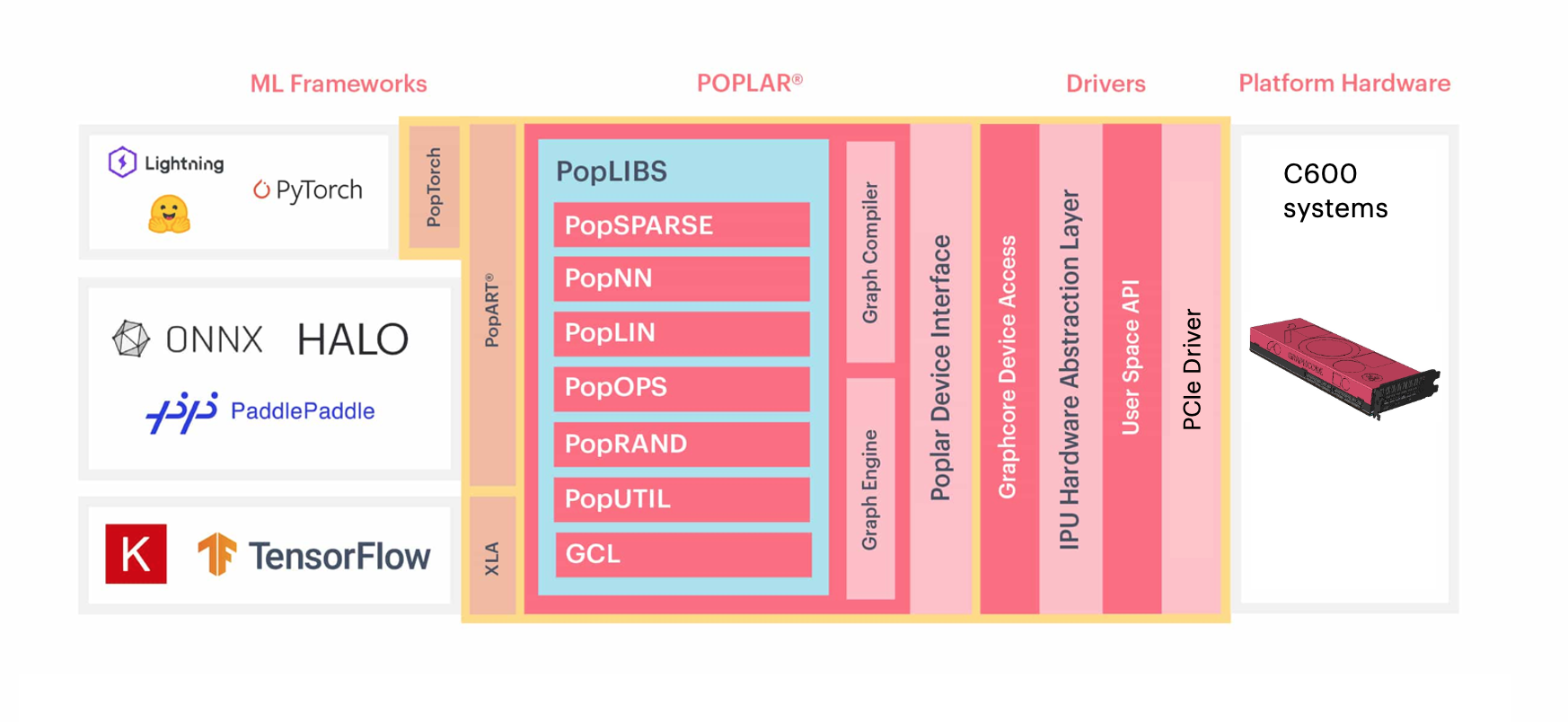
Fig. 1.3 C600 software
C600 software |
|
|---|---|
ML frameworks |
TensorFlow, Keras, PyTorch, Pytorch Lightning, Hugging Face, PaddlePaddle, Halo, and ONNX |
Deployment options |
Bare metal (Linux), VM (HyperV), containers (Docker) |
Graphcore Communication Library (GCL) |
IPU-optimized communication and collective library integrated with the Poplar SDK stack |
PopVision |
Visualization and analysis tools |
To see a full list of supported OS, VM and container options go to the Graphcore support portal https://www.graphcore.ai/support.
1.9. Main features
Feature |
Specifications |
PCIe interface |
Dual-slot full-height PCIe Gen 4 card supporting 64 GB/s data transmission |
Processor |
Intelligence Processing Unit |
Operating Frequency |
1.5 GHz |
Thermal Design Power (TDP) |
185 W, maximum power 252 W |
PCIe edge connector |
DC 12 V and 3.3 V |
Multiple C600 card support |
IPU-Link cables |