2. Installation
Installing the C600 IPU-Processor PCIe card requires the following steps:
Determine air-flow requirements (Section 2.1, Airflow requirements)
Determine which fastenings and supports are required (Section 2.2, Extender brackets for C600 card support)
Power down the system and allow the equipment to cool
Insert the card into the PCIe slot and attach the 12 V power supply cable (Section 2.3, Inserting a C600 card)
If using multiple cards together, attach IPU-Link cables (Section 2.5, IPU-Link cables)
Install software (Section 2.6, Installing host software)
If you need to remove a C600 card there are instructions on how to do this in Section 2.4, Removing a C600 card.
2.1. Airflow requirements
The C600 card is passively cooled when installed in a suitable chassis enclosure. Fans within the chassis housing the C600 card(s) need to deliver sufficient airflow to keep the cards below their maximum operational temperature threshold, removing up to 250 W of heat per C600 card in cases where the power cap is set to the maximum allowed.
Table 2.1 shows the minimum airflow requirements per card.
Note
Airflow requirements vary with inlet temperature.
Card inlet maximum air temperature |
35°C |
Minimum airflow per card |
30 cubic feet/minute (850 litres/min) |
The C600 card may operate at higher temperatures than 35°C (up to 55°C) but in that case performance will be throttled to maintain IPU temperature.
2.2. Extender brackets for C600 card support
When seated in a chassis, C600 cards must be secured at both ends, which requires the use of extender brackets.
Graphcore can supply different extender brackets to suit different chassis. Contact your Graphcore representative or use the Graphcore support portal to discuss which extender brackets are required for your system.
There are four different types of extender bracket supplied by Graphcore — Straight extender, Thumbscrew extender, Offset extender and Enhanced straight extender with retention plunger. The bracket attaches to the C600 card at the same end as the power socket. This enables your C600 cards to be seated securely in the PCIe connector slot. Which extender bracket you require will depend on the chassis that the C600 cards are being installed in.
2.2.1. Straight extender
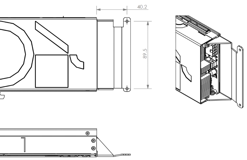
Fig. 2.1 C600 straight extender bracket
2.2.2. Thumbscrew extender
The thumbscrew itself is of type UNC 6-32.
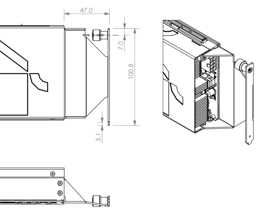
Fig. 2.2 C600 thumbscrew extender bracket
2.2.3. Offset extender
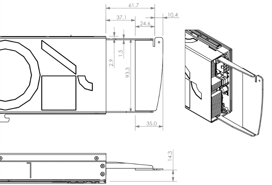
Fig. 2.3 C600 offset extender bracket
2.2.4. Enhanced straight extender with retention plunger
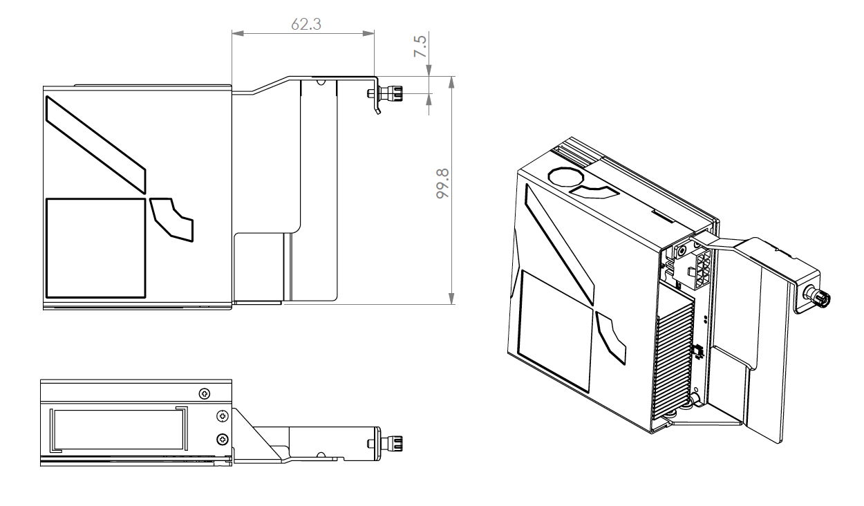
Fig. 2.4 C600 enhanced straight extender bracket with retention plunger
2.3. Inserting a C600 card
Follow these instructions to insert your C600 card(s) into your chassis.
2.3.1. Seating the card in the PCIe slot
Make sure the system has been powered down and the equipment has had time to cool. Observe anti-static precautions when handling C600 cards.
Depending on the type of enclosure you’re using, you may find it easier to connect the 12 V power connector before or after you seat the PCIe edge connector in the PCIe slot.
Align the notch in the PCIe connector with the key in the PCIe slot to ensure correct orientation.
With the PCIe edge connector facing downward, push the card firmly into the PCIe socket in the chassis.
Attach the 12 V power connector. See the pin-out diagram in Section 1.3.1, 12 V auxiliary power supply specification for details.
Secure the card at both ends as appropriate for your chassis design and extender brackets.
Attach the IPU-Link cables if you are joining multiple C600 cards together (Section 2.5, IPU-Link cables).
2.4. Removing a C600 card
Should you need to remove an installed C600 card, follow these steps:
Turn off all the power to the chassis, and, if it has been powered on recently, allow the equipment to cool. Observe anti-static precautions when handling C600 cards.
Remove the IPU-Link cables from the cards (if fitted). See Section 2.5, IPU-Link cables for how to handle IPU-Link cables.
Unfasten any securing mechanisms (for example screws or clamps) that hold the card securely in the chassis.
Holding both ends of the card, gently pull it out of the PCIe socket, using a very slight rocking motion. Ensure that you don’t rotate the card too far in the PCIe socket so that one end comes out before the other, otherwise you may damage the connectors.
2.5. IPU-Link cables
If you are using multiple C600 cards in a cluster, you’ll need to join them together using the IPU-Link cables. These cables allow the IPU devices on the C600 cards to communicate at far higher bandwidth than is available over the PCIe bus alone.
2.5.1. IPU-Link cable layout
The following diagram shows the standard IPU-Link configuration for eight C600 cards in a linear configuration, as viewed from above:
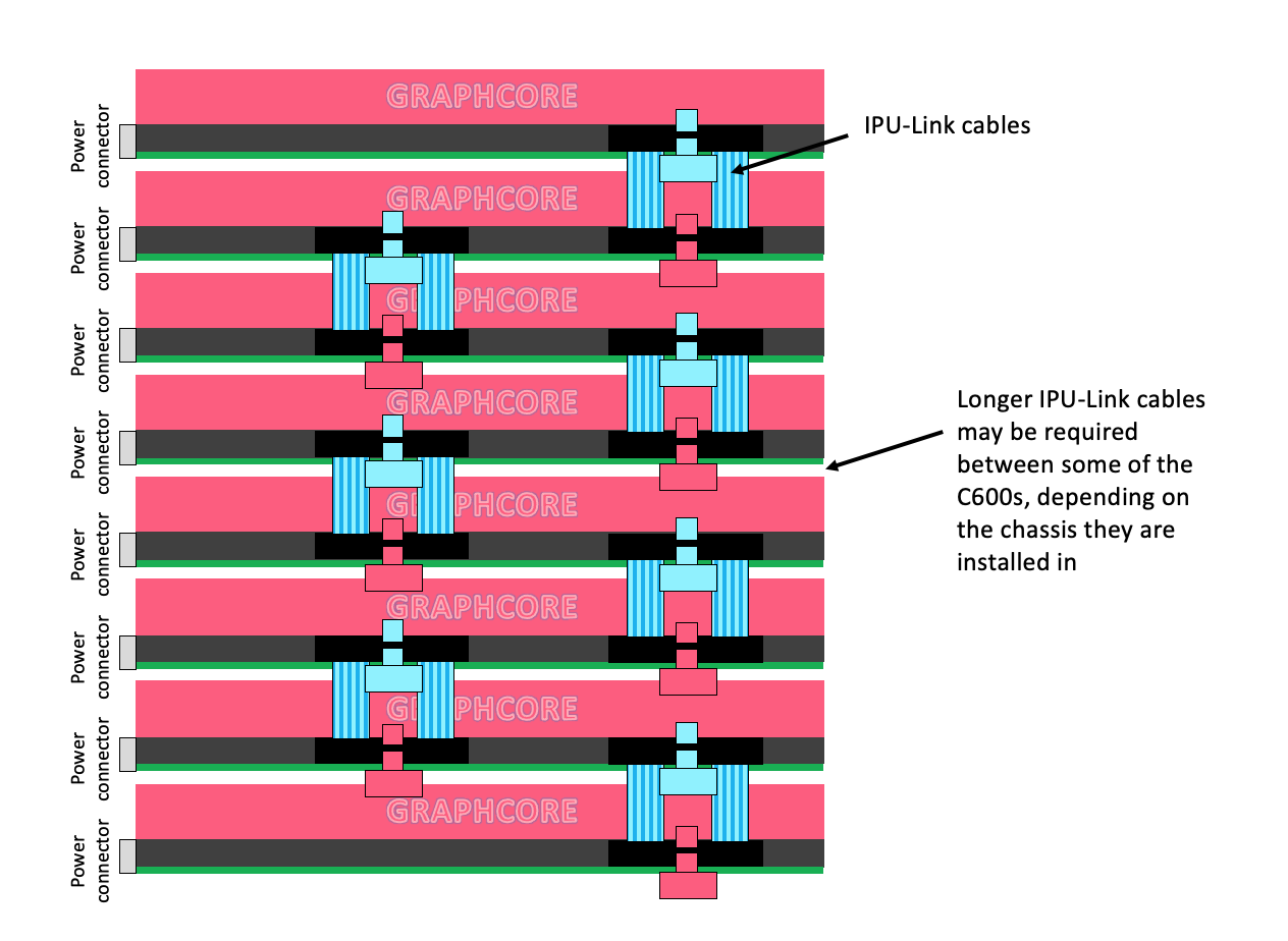
Fig. 2.5 Standard IPU-Link configuration for eight C600 cards in a linear configuration
Warning
You must only use the IPU-Link cables supplied by Graphcore, which have been customised and are qualfied for use with the C600 cards.
2.5.2. Inserting an IPU-Link cable
To install an IPU-Link cable:
Make sure the power has been switched off on the host machine.
With the Graphcore text on the side of the card facing you, the cables are orientated with the blue tab closest to you.
Press down one end of the cable at a time until you hear the snap of the connector seating fully into the socket.
2.5.3. Removing an IPU-Link cable
Note
Take care when removing IPU-Link cables — you must ensure that the connectors on each end are not strained.
To remove an IPU-Link cable:
Pull the coloured tabs to release the retaining catch as the connector is pulled upwards.
2.5.4. Testing IPU-Link cable connections
The system software tests the electrical signal integrity of the IPU-Link cables. These tests are performed automatically while the C600 cards are in use and an error will be reported if any of the connections between cards are not working.
2.6. Installing host software
Once you have installed all your C600 cards, you then need to install the software so you can test platform functionality and start using your C600 cards.
Host software for operating C600 cards is available from Graphcore. Visit https://graphcore.ai/downloads to download all software components.
You will need to download:
PCIe drivers to enable the host machine to communicate with the C600 (currently included in the Poplar SDK tarball)
C600 card firmware updater
Poplar SDK, Graphcore’s machine learning software stack for the IPU
(Optional) A Docker container for the framework you want to use, available from Docker Hub
See the Poplar Quick Start for details of installation and use of the Poplar graph programming framework.
You can find more information about the frameworks you can use for programming IPUs in our Software Documents.
You can use the IPU Programmer’s Guide for more information about programming on IPUs.
There is more information about using Docker containers in Using IPUs from Docker.
Note
New software versions, as well as additional software, are routinely released so it is important to check regularly to make sure that your system is up to date.
2.7. Standards compliance
EMC standards |
Emissions: FCC CFR 47, EN55032, EN61000-3-2, EN61000-3-3 |
Immunity: EN55035, EN61000-4-2, EN61000-4-3, EN61000-4-4, EN61000-4-5, EN61000-4-6, EN61000-4-8, EN61000-4-11 |
|
Safety standards |
CB: IEC 60950-1, IEC 62368-1 2nd edition, IEC 62368-1 3rd edition. |
UL: UL 62368-1 3rd |
|
cUL: CAN/CSA C22.2 No. 62368-1: 19 3rd |
|
Certifications |
North America (FCC), Europe (CE), UK (UKCA), China (CQC) GB/T 9254.1-2021 |
United States (UL), Canada (cUL), International (CB) CB-62368, CB-60950 |
|
Environmental standards |
EU 2011/65/EU RoHS Directive, XVII REACH 1907/2006, 2012/19/EU WEEE Directive |
2.7.1. Waste Electrical and Electronic Equipment (WEEE) Directive
The European Directive 2012/19/EU on Waste Electrical and Electronic Equipment (WEEE) states that these appliances should not be disposed of as part of the routine solid urban waste cycle, but collected separately in order to optimise the recovery and recycling flow of the materials they contain, while also preventing potential damage to human health and the environment arising from the presence of potentially hazardous substances.
The crossed-out bin symbol is printed on all products as a reminder that the product must not be disposed of with your other household waste.
Owners of electrical and electronic equipment (EEE) should contact their local government agencies to identify local WEEE collection and treatment systems for the environmental recycling and/or disposal of their end of life computer products. For more information on proper disposal of these devices, refer to the public utility service.
2.8. Ordering information
To enquire about ordering C600 PCIe cards, contact c600-support@graphcore.ai.