2. IPU-M2000 BMC specification
The IPU-M2000 baseboard management controller (BMC) runs software based on the OpenBMC project.
The responsibilities of the BMC software stack are to control, monitor and manage system hardware, including power, sensors, inventories and event logging.
You can control and monitoring the system, via the BMC, using a variety of user interfaces such as a command line interface (CLI), graphical user interface (GUI), REST API, IPMI and Redfish.
2.1. BMC subsystem
A block diagram of the IPU-M2000, showing the BMC subsystem, is shown in Fig. 2.1.
The physical components in the BMC subsystem are:
ASPEED AST2520 baseboard management controller
System FPGA
128 MB serial boot flash
1 GB of DDR4 DRAM
One USB port — Micro-USB management interface, see Fig. 13.1
Two 1 GbE ports — at boot the BMC Ethernet interface (eth0) is set to 100 Mbps, full-duplex, auto-negotiation on
Two PSU interfaces for monitoring the state of the power supplies
Five fan interfaces for controlling and measuring the speed of the system cooling fans
LEDs used to indicate status
2.1.1. System FPGA
The FPGA is mainly a status and control signal concentrator. It ensures that those control signals are always in a safe state. In addition, it provides hardware monitoring and protection for any thermal or voltage abnormalities. It also controls the sequencing of supply voltages, clocks and reset signals.
2.1.2. LEDs
There are three LEDs used to indicate status:
Green indicates normal operation status
White is used to identify a specific IPU-M2000 in a system
Yellow indicates various error conditions:
Temperature alert detected
Standby voltages detected failing
PSUs detected failing
Connector domain detected failing
GW 1 domain detected failing
IPU 1 and 2 or IPU 3 and 4 domains detected failing
Fan fail detected (too few fans or fans running too slow)
No profile configuration found in flash
BMC flash not trusted
2.2. BMC functions
The BMC supports the following system management functions:
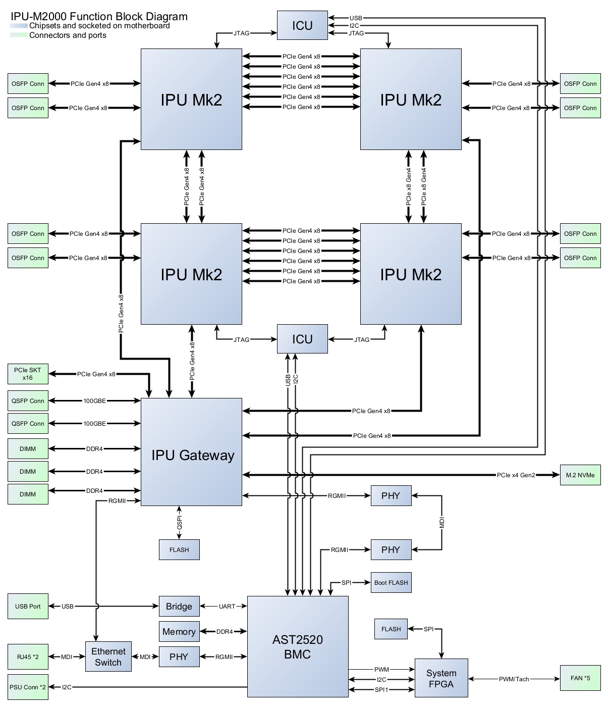
Fig. 2.1 IPU-M2000 BMC block diagram