2. Bow Pod64 reference design components
This section describes the components in each Bow Pod64 reference design system. Each Bow Pod64 contains:
1 Server (default configuration is one host server, up to four can be supported)
2 Switches (one 1GbE management switch and one 100GbE ToR switch)
1 Rack
2.1. Bow-2000 IPU-Machines
2.1.1. Overview
There are 16 Bow-2000 IPU-Machines in each Bow Pod64 making a total of 64 Bow IPUs: 4 per Bow-2000. The Bow-2000 front panel contains:
2 RNIC ports
8 IPU-Link ports
2 Management GbE ports (BMC + IPU-Gateway management ports)
2 GW-Link ports
8 Sync-Link ports
3 LED indicators
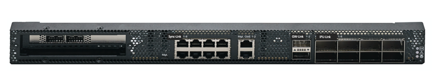
Fig. 2.1 Front panel
The Bow-2000 back panel contains:
2 power connectors per Bow-2000
5 fan units
5 LED indicators
Unit QR code
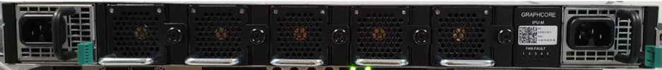
Fig. 2.2 Back panel
2.1.2. QR code label
There is a QR code label on the back panel of each Bow-2000. The QR code contains the following information for each Bow-2000:
Company name (Graphcore)
Serial number
Part number
BMC Ethernet MAC address
IPU-Gateway Ethernet MAC address
URL for Graphcore support portal

Fig. 2.3 QR code label on Bow-2000
2.1.3. LED indicators
The Bow-2000 has LED indicators on both sides of the chassis.
Rear side LEDs
The rear side LEDs (Fig. 2.4) indicate the state of the 5 fans on the Bow-2000. All the indicators should normally be off. A lit LED (amber) indicates a fan module fault and the corresponding fan module should be replaced as soon as possible to maintain maximum cooling.
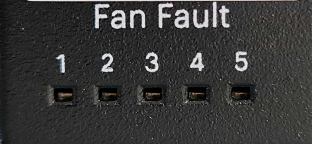
Fig. 2.4 Rear side LED indicators
Front side LEDs
The front side LEDs indicate the status of the Bow-2000. Fig. 2.5 and Table 2.1 show the colour scheme and indications.
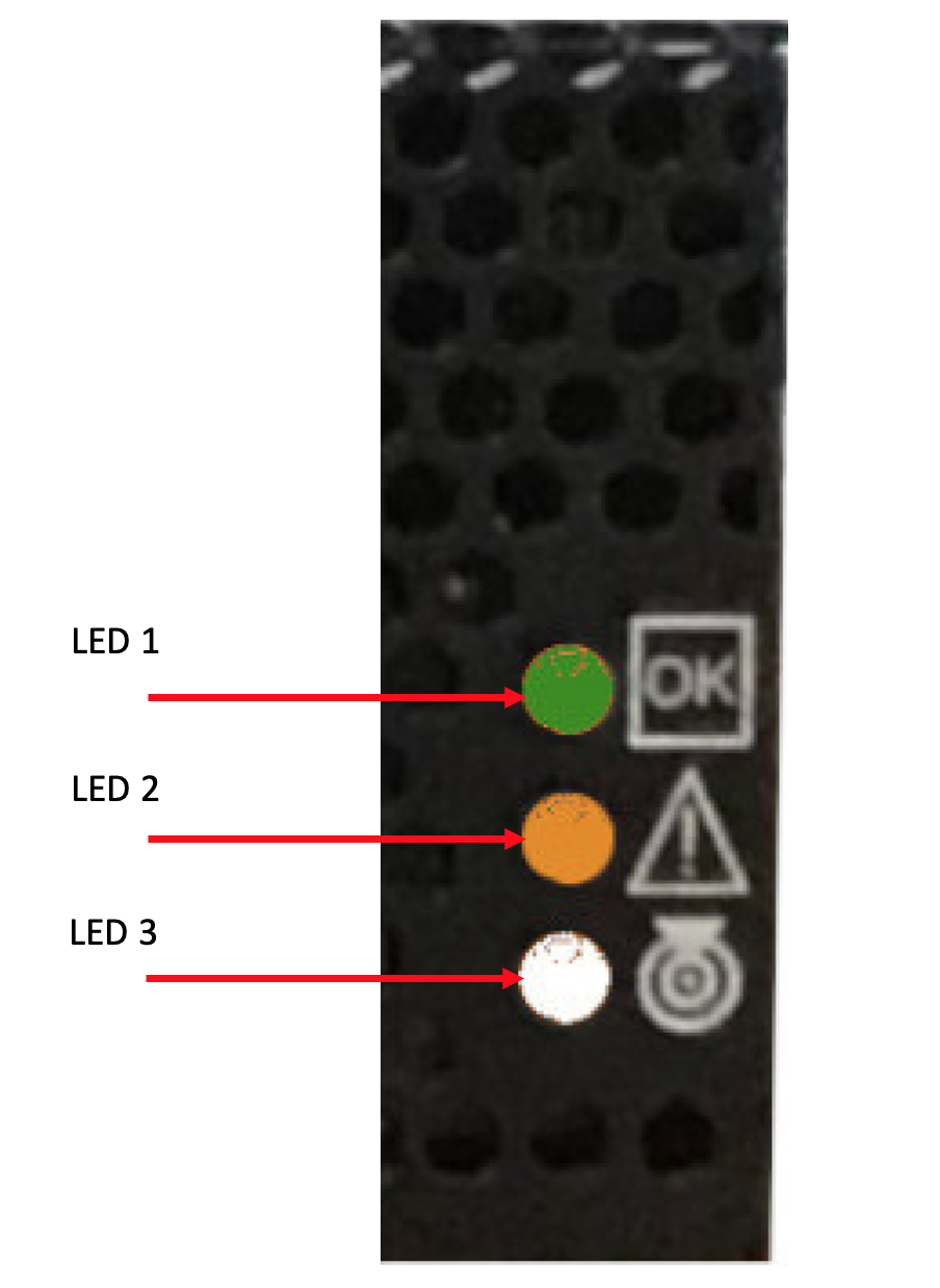
Fig. 2.5 Front side LEDs
LED |
Colour |
Function |
1 |
Green |
“OK”, ”Normal”, ”Satisfactory operation”, ”Active”, or “In service” |
10 Hz: BMC running on flash (instruction fetch from flash) |
||
2 Hz: BMC running on DRAM without interrupt enabled (instruction fetch from DRAM) |
||
0.5 Hz: BMC running on DRAM with interrupt enabled (system in standby mode) |
||
0.1 Hz: BMC abnormal mode, some interrupts are not serviced for over 2 seconds |
||
Steady green light: System operational |
||
2 |
Amber |
“Attention” or “Service action required” |
3 |
White |
“Here I am”,”This is the item being sought” or “Unit ID” |
2.2. Server
The default configuration of the Bow Pod64 uses a single PowerEdge R6525 server but up to four servers can be used. Contact Graphcore sales for details of other supported server types. This document describes the default server (PowerEdge R6525) installation only. Other servers may have different installation requirements.
The default server configuration is described in Section 4.1, Server configuration.
2.3. Switches
Each Bow Pod64 contains two network switches serving different purposes.
2.3.1. 100GE RoCE/RDMA switch (ToR switch)
The 100GbE RoCE/RDMA switch (also referred to as the ToR switch) is used by the end user’s machine learning (ML) jobs as a data-plane, connecting the host servers running the Poplar® SDK with the IPUs running the ML model in the Bow-2000 IPU-Machines. The default ToR switch is an Arista DCS-7060CX-32S-F. Contact Graphcore sales for details of other supported switch types. This document describes the default switch (7060CX) installation only. Other switches may have different installation requirements.
2.3.2. 1GbE management switch
The 1GbE management switch is used for connecting the management ports together inside the rack. The default management switch is an Arista DCS-7010T-48-F. Contact Graphcore sales for details of other supported switch types. This document describes the default switch (7010T) installation only. Other switches may have different installation requirements.
2.4. Power distribution units
Two power distribution units (PDUs) are installed in each Bow Pod64. The default unit is an APC AP8886.
2.5. Rack
The Bow-2000s, servers, switches, and PDUs are installed in an APC AR3300SP rack. This rack has a packing system designed to safely transport and unload the rack.
It is important to follow the instructions carefully when packing or unpacking the rack.
2.6. Supplementary mounting components
The supplementary components listed below also need to be installed.
Cable organizer
Blanking panel
2.7. Cables
Each Bow Pod64 has three types of cabling:
RJ45 cables
OSFP cables
QSFP cables
2.7.1. RJ45 cables
Red: Bow-2000 to Bow-2000 within-rack IPU-Link connectivity
Blue: Connecting Bow-2000s to the management switch (BMC + IPU-Gateway management)
Blue: Connecting servers to the management switch
Yellow for connecting Bow-2000s to the management switch (BMC only management)
2.7.2. OSFP cables
Bow-2000 to Bow-2000 (IPU-Link) connectivity
2.7.3. QSFP cables
Bow-2000 to ToR switch connectivity
For server to ToR switch connectivity
All cable connections are described in Section 3, Rack assembly.