4. General server installation and switch configuration
This chapter describes how to install and configure the software, including the OS, on the server(s) in a Bow Pod64 system. We also describe how to configure the network switches.
Note
Ansible playbooks for the server installation and files for switch configuration can be provided on request: please contact Graphcore support. These templates may need to be adapted to match any site-specific differences.
4.1. Server configuration
The server and Bow Pod64 configuration consists of the following main steps:
Provide appropriate server hardware (Hardware recommendations), according to the approved server list available from Graphcore.
This should include supported storage (Storage configuration recommendations) and supported memory configurations (Memory configuration recommendations)
Configure server BIOS appropriately (BIOS configuration)
Install the appropriate OS and packages (Operating system installation)
Setup default user accounts and permissions (User accounts and groups)
Setup a DHCP server (DHCP Service (Dynamic Host Configuration Protocol))
Setup a Syslog service (Rsyslog service)
Setup an NTP service (NTP service (Network Time Protocol))
Final configuration: security and default folders (Other configuration files and folders)
Note
If your Bow Pod64 system has more than one server, all servers should be set up identically, as described in this chapter.
4.1.1. Hardware recommendations
The Bow Pod64 system reference design uses a single PowerEdge R6525 server but up to four servers can be connected. Contact Graphcore sales or refer to the list of approved servers for details of other supported server types. This document describes the default server (PowerEdge R6525) installation only. Other servers may have different installation requirements.
The recommended configuration of the Dell R6525 is as follows:
Dell R6525 containing dual AMD EPYC 7742 processors
16x 32GbE RDIMM PC4-25600 ECC registered dual-rank X4 1.2v
2x 480GbE SSD-SATA 6Gbps 2.5 inch hot-swap
7x 1TB NVME SSD PCIe 4x 3.1
Dual port Gigabit BASE-T PCIe
Single/dual port Mellanox ConnectX-5 EN 100Gb/s Ethernet
4.1.2. Storage configuration recommendations
The recommendation is to have two types of server storage: SSD-SATA for the operating system and NVME SSD for data storage.
Operating system:
2x 480GbE SSD-SATA units as a RAID 1 via hardware controller
Partitioned to use ext4 file system
Data storage:
7x 1TB NVME SSD units as a logical RAID 6 managed with MDADM
Partitioned to use xfs file system
4.1.3. Memory configuration recommendations
The DIMMs should be installed in a fully symmetric configuration, as recommended by Dell for maximum performance. The recommended configuration has 8 DIMMs per processor, as shown below.

Fig. 4.1 DIMM memory configuration
4.1.4. BIOS configuration
Various BIOS settings can impact the performance of the system. The recommended settings are shown in Table 4.1.
Setting |
BIOS 1.2.11 |
BIOS 1.4.8 or later |
|---|---|---|
LogicalProc |
Enabled |
Enabled |
ProcVirtualization |
Enabled |
Enabled |
IommuSupport |
Disabled |
See below |
L1StreamHwPrefetcher |
Enabled |
Enabled |
L2StreamHwPrefetcher |
Enabled |
Enabled |
MadtCoreEnumeration |
Linear |
Linear |
NumaNodesPerSocket |
4 |
4 |
CcxAsNumaDomain |
Disabled |
Disabled |
CpuMinSevAsid |
1 |
1 |
ProcCcds |
All |
All |
CcdCores |
All |
All |
EmbSata |
AhciMode |
AhciMode |
BIOS 1.4.8 or later does not configure IOMMU directly. Instead, you need to add iommu=off to the kernel boot params in /etc/default/grub and then run update-grub.
4.1.5. Operating system installation
This document describes the following operating systems supported by version 2.6 of the IPU-M software. Please contact your Graphcore representative or use the support portal for information about support for other operating systems or other versions of the IPU-M software.
Note
These operating systems are supported by the IPU-M software and are different to the operating systems supported by the Poplar SDK. Refer to the IPU-Machine System Software 2.6.0 Release Notes and the Poplar SDK 3.4.0 Release Notes for OS support information.
Note
If you are manually installing these packages, you can copy the list of packages into a text file, and run:
$ sudo apt update
$ xargs -a reqs.txt sudo apt-get install
where reqs.txt contains the list of packages.
This document also lists the Python packages required for these operating systems.
Ubuntu 18.04 packages
In order to have a stable system where IPU related software can run, several packages need to be installed (see Table 4.2) via the Aptitude package manager tool. Other packages may be required for local requirements.
autoconf |
golang-go |
minicom |
rsyslog |
automake |
htop |
moreutils |
screen |
bc |
ibverbs-utils |
net-tools |
sshpass |
build-essential |
ipmitool |
netcat |
subversion |
ccache |
jq |
ntp |
swig |
clang |
kcachegrind |
openjdk-8-jdk |
sysfsutils |
cmake |
libaio-dev |
parallel |
tar |
direnv |
libboost-all-dev |
pciutils |
tmux |
dkms |
libeigen3-dev |
perl |
u-boot-tools |
emacs |
libjson-c-dev |
php-cli |
unzip |
ethtool |
libjson-c-doc |
php-curl |
valgrind |
exuberant-ctags |
libpci-dev |
policykit-1 |
vim |
flex |
libpixman-1-dev |
protobuf-compiler |
virtualenv |
g++ |
libprotobuf-dev |
python3 |
wdiff |
gawk |
libtool |
python3-dev |
wget |
gcc |
lldpad |
python3-pip |
zip |
gdb |
lldpd |
qtcreator |
|
git |
m4 |
rdma-core |
Ubuntu 20.04 packages
autoconf |
golang-go |
minicom |
rsyslog |
automake |
htop |
moreutils |
screen |
bc |
ibverbs-utils |
net-tools |
sshpass |
build-essential |
ipmitool |
netcat |
subversion |
ccache |
jq |
ntp |
swig |
clang |
kcachegrind |
openjdk-8-jdk |
sysfsutils |
cmake |
libaio-dev |
parallel |
tar |
direnv |
libboost-all-dev |
pciutils |
tmux |
dkms |
libeigen3-dev |
perl |
u-boot-tools |
emacs |
libjson-c-dev |
php-cli |
unzip |
ethtool |
libjson-c-doc |
php-curl |
valgrind |
exuberant-ctags |
libpci-dev |
policykit-1 |
vim |
flex |
libpixman-1-dev |
protobuf-compiler |
virtualenv |
g++ |
libprotobuf-dev |
python3 |
wdiff |
gawk |
libtool |
python3-dev |
wget |
gcc |
lldpad |
python3-pip |
zip |
gdb |
lldpd |
qtcreator |
|
git |
m4 |
rdma-core |
CentOS 7.6 packages
In order to have a stable system where IPU related software can run, several packages need to be installed (see Table 4.4) via the yum configuration manager. Other packages may be required for local requirements.
bc |
htop |
moreutils |
rdma-core |
boost-devel |
ipmitool |
nano |
rsyslog |
centos-release-scl |
java-latest-jdk |
nc |
screen |
clang |
jq |
net-tools |
snapd |
cmake |
json-c-devel |
ntp |
sshpass |
containerd.io |
json-c-doc |
parallel |
sysfsutils |
devtoolset-7 |
libaio-devel |
pciutils-devel |
tmux |
dhcp |
libibverbs-utils |
php-cli |
vim |
dkms |
libuser |
protobuf-devel |
wdiff |
eigen3 |
lldpad |
python3-pip |
wget |
emacs |
lldpd |
python36 |
|
golang-go |
minicom |
qt5-qbase |
Python packages
Several Python packages are also required for both operating system installations. They can be installed using the pip installation tool.
autograd |
numpy |
pytest |
setuptools |
boto3 |
paramiko |
pyyaml |
virtualenv |
jstyleson |
pep8 |
recommonmark |
wheel |
lxml |
pexpect |
requests |
yapf |
mock |
pylint |
scp |
4.1.6. User accounts and groups
Table 4.6 contains details of the accounts that are required as part of the default server configuration:
Account |
Description |
|---|---|
root |
A root user account secured with a password is recommended. |
itadmin |
An admin account secured with a password is recommended. Home directory located at |
ipuuser |
An account dedicated to IPU software and Bow Pod management software is mandatory. Home directory located at |
poplaruser |
An account dedicated to Poplar software is mandatory. Home directory located at |
Table 4.7 gives the default usernames provided on the Bow Pod64 system.
Log in to |
Username |
|---|---|
Bow-2000 BMC OS |
root |
Bow-2000 IPU-Gateway OS |
itadmin |
Server as Poplar SDK user |
poplaruser |
Server as Bow Pod admin user |
ipuuser |
Server as IT admin user |
itadmin |
Server iDRAC port |
root |
100GbE RDMA switch |
admin |
1GbE Management switch |
admin |
PDU |
apc |
The default passwords are available from Graphcore support portal.
Table 4.8 contains the required groups provided on the Bow Pod64 system.
Groups |
Description |
|---|---|
root |
A root group to locate the root account is mandatory. |
dhcpd |
A group to allocate the DHCP service is mandatory (this is usually configured automatically while installing the DHCP service). |
ipugroup |
A group to allocate ipuuser is mandatory. |
poplargroup |
A group to allocate poplaruser is mandatory. |
ipupodgroup |
A group to allocate both ipuuser and poplaruser is mandatory. |
Note that all users need to have unique user IDs and group IDs.
4.1.7. DHCP Service (Dynamic Host Configuration Protocol)
An ISC-DHCP-Server service (Table 4.9) is recommended to provide DHCP network configuration to Bow-2000s. It can be installed from the Ubuntu or CentOS public repositories.
Name |
Type |
User |
Group |
Access |
Description |
|---|---|---|---|---|---|
/etc/dhcp/ |
folder |
root |
dhcpd |
0755 |
DHCP related files |
/etc/dhcp/dhcpd.d/ |
folder |
root |
dhcpd |
0755 |
Bow-2000 network configuration files |
Ubuntu: /etc/default/isc-dhcp-server |
file |
root |
root |
0644 |
Network interfaces which DHCP will use |
CentOS: /etc/sysconfig/dhcpd |
file |
root |
root |
0644 |
Network interfaces which DHCP will use |
/etc/dhcp/dhcpd.d/vlan-11.conf |
file |
root |
dhcpd |
0644 |
Mapping between desired IPs and Bow-2000 100GbE RNIC |
/etc/dhcp/dhcpd.d/vlan-13.conf |
file |
root |
dhcpd |
0644 |
Mapping between desired IPs and Bow-2000 1GbE BASE-T interfaces |
/etc/dhcp/dhcpd.d/vlan-99.conf |
file |
root |
dhcpd |
0644 |
Mapping between desired IPs and management 1GbE BASE-T interfaces MAC addresses |
/etc/dhcp/dhcpd.conf |
file |
root |
dhcpd |
0644 |
Main DHCP server configuration file |
DHCP file templates
Note
The configuration files below are just examples. You must update the MAC addresses to match those in your system.
Ubuntu: /etc/default/isc-dhcp-server
INTERFACES=”eno3 enp59s0f1”
CentOS: /etc/sysconfig/dhcpd
DHCPDARGS="em4 p1p2
/etc/dhcp/dhcpd.d/vlan-11.conf (file)
# Example of content. Add all RNICs below using this format
#
#host ipum1mx  {hardware ethernet aa:bb:cc:dd:ee:ff;    fixed-address 10.1.5.1;}
#host ipum2mx  {hardware ethernet aa:bb:cc:dd:ee:ff;    fixed-address 10.1.5.2;}
#host ipum3mx  {hardware ethernet aa:bb:cc:dd:ee:ff;    fixed-address 10.1.5.3;}
#host ipum4mx  {hardware ethernet aa:bb:cc:dd:ee:ff;    fixed-address 10.1.5.4;}
#host ipum5mx  {hardware ethernet aa:bb:cc:dd:ee:ff;    fixed-address 10.1.5.5;}
#host ipum6mx  {hardware ethernet aa:bb:cc:dd:ee:ff;    fixed-address 10.1.5.6;}
#host ipum7mx  {hardware ethernet aa:bb:cc:dd:ee:ff;    fixed-address 10.1.5.7;}
#host ipum8mx  {hardware ethernet aa:bb:cc:dd:ee:ff;    fixed-address 10.1.5.8;}
#host ipum9mx  {hardware ethernet aa:bb:cc:dd:ee:ff;    fixed-address 10.1.5.9;}
#host ipum10mx {hardware ethernet aa:bb:cc:dd:ee:ff;    fixed-address 10.1.5.10;}
#host ipum11mx {hardware ethernet aa:bb:cc:dd:ee:ff;    fixed-address 10.1.5.11;}
#host ipum12mx {hardware ethernet aa:bb:cc:dd:ee:ff;    fixed-address 10.1.5.12;}
#host ipum13mx {hardware ethernet aa:bb:cc:dd:ee:ff;    fixed-address 10.1.5.13;}
#host ipum14mx {hardware ethernet aa:bb:cc:dd:ee:ff;    fixed-address 10.1.5.14;}
#host ipum15mx {hardware ethernet aa:bb:cc:dd:ee:ff;    fixed-address 10.1.5.15;}
#host ipum16mx {hardware ethernet aa:bb:cc:dd:ee:ff;    fixed-address 10.1.5.16;}
/etc/dhcp/dhcpd.d/vlan-13.conf
# Example of content. Add all BMCs and Gws below using this format
#
#host ipum1bmc  {hardware ethernet a0:b0:c0:d0:e0:f0;    fixed-address 10.1.1.1;}
#host ipum1gw   {hardware ethernet a1:b1:c1:d1:e1:f1;    fixed-address 10.1.2.1;}
#host ipum2bmc  {hardware ethernet a0:b0:c0:d0:e0:f0;    fixed-address 10.1.1.2;}
#host ipum2gw   {hardware ethernet a1:b1:c1:d1:e1:f1;    fixed-address 10.1.2.2;}
#host ipum3bmc  {hardware ethernet a0:b0:c0:d0:e0:f0;    fixed-address 10.1.1.3;}
#host ipum3gw   {hardware ethernet a1:b1:c1:d1:e1:f1;    fixed-address 10.1.2.3;}
#host ipum4bmc  {hardware ethernet a0:b0:c0:d0:e0:f0;    fixed-address 10.1.1.4;}
#host ipum4gw   {hardware ethernet a1:b1:c1:d1:e1:f1;    fixed-address 10.1.2.4;}
#host ipum5bmc  {hardware ethernet a0:b0:c0:d0:e0:f0;    fixed-address 10.1.1.5;}
#host ipum5gw   {hardware ethernet a1:b1:c1:d1:e1:f1;    fixed-address 10.1.2.5;}
#host ipum6bmc  {hardware ethernet a0:b0:c0:d0:e0:f0;    fixed-address 10.1.1.6;}
#host ipum6gw   {hardware ethernet a1:b1:c1:d1:e1:f1;    fixed-address 10.1.2.6;}
#host ipum7bmc  {hardware ethernet a0:b0:c0:d0:e0:f0;    fixed-address 10.1.1.7;}
#host ipum7gw   {hardware ethernet a1:b1:c1:d1:e1:f1;    fixed-address 10.1.2.7;}
#host ipum8bmc  {hardware ethernet a0:b0:c0:d0:e0:f0;    fixed-address 10.1.1.8;}
#host ipum8gw   {hardware ethernet a1:b1:c1:d1:e1:f1;    fixed-address 10.1.2.8;}
#host ipum9bmc  {hardware ethernet a0:b0:c0:d0:e0:f0;    fixed-address 10.1.1.9;}
#host ipum9gw   {hardware ethernet a1:b1:c1:d1:e1:f1;    fixed-address 10.1.2.9;}
#host ipum10bmc {hardware ethernet a0:b0:c0:d0:e0:f0;    fixed-address 10.1.1.10;}
#host ipum10gw  {hardware ethernet a1:b1:c1:d1:e1:f1;    fixed-address 10.1.2.10;}
#host ipum11bmc {hardware ethernet a0:b0:c0:d0:e0:f0;    fixed-address 10.1.1.11;}
#host ipum11gw  {hardware ethernet a1:b1:c1:d1:e1:f1;    fixed-address 10.1.2.11;}
#host ipum12bmc {hardware ethernet a0:b0:c0:d0:e0:f0;    fixed-address 10.1.1.12;}
#host ipum12gw  {hardware ethernet a1:b1:c1:d1:e1:f1;    fixed-address 10.1.2.12;}
#host ipum13bmc {hardware ethernet a0:b0:c0:d0:e0:f0;    fixed-address 10.1.1.13;}
#host ipum13gw  {hardware ethernet a1:b1:c1:d1:e1:f1;    fixed-address 10.1.2.13;}
#host ipum14bmc {hardware ethernet a0:b0:c0:d0:e0:f0;    fixed-address 10.1.1.14;}
#host ipum14gw  {hardware ethernet a1:b1:c1:d1:e1:f1;    fixed-address 10.1.2.14;}
#host ipum15bmc {hardware ethernet a0:b0:c0:d0:e0:f0;    fixed-address 10.1.1.15;}
#host ipum15gw  {hardware ethernet a1:b1:c1:d1:e1:f1;    fixed-address 10.1.2.15;}
#host ipum16bmc {hardware ethernet a0:b0:c0:d0:e0:f0;    fixed-address 10.1.1.16;}
#host ipum16gw  {hardware ethernet a1:b1:c1:d1:e1:f1;    fixed-address 10.1.2.16;}
/etc/dhcp/dhcpd.d/vlan-99.conf
# Example of content. Add all Management devices below using this format
#
#host MgmtDevice1 {   hardware ethernet a2:b2:c2:d2:e2:f2;    fixed-address 10.1.6.x;}
/etc/dhcp/dhcpd.conf
default-lease-time 600;
max-lease-time 1200;
ddns-update-style none;
authoritative;
log-facility local7;
subnet 10.1.4.0 netmask 255.255.254.0 {
    option subnet-mask         255.255.254.0;
    range                      10.1.5.200 10.1.5.254;
    option ntp-servers         10.1.5.101;
}
include "/etc/dhcp/dhcpd.d/vlan-11.conf";
subnet 10.1.0.0  netmask 255.255.252.0 {
    option subnet-mask         255.255.252.0;
    range                      10.1.3.200 10.1.3.254;
    option ntp-servers         10.1.5.101;
}
include "/etc/dhcp/dhcpd.d/vlan-13.conf";
subnet 10.1.6.0 netmask 255.255.254.0 {
    option subnet-mask         255.255.254.0;
    range                      10.1.6.200 10.1.6.254;
}
include "/etc/dhcp/dhcpd.d/vlan-99.conf";
The DHCP service is started using:
$ sudo systemctl enable dhcp
$ sudo systecmtl start dhcp
4.1.8. Rsyslog service
The rsyslog service (Table 4.10) is a software utility for forwarding log messages in an IP network.
Name |
Type |
User |
Group |
Access |
Description |
|---|---|---|---|---|---|
/etc/rsyslog.d |
folder |
root |
root |
0755 |
Rsyslog tool configuration folder |
/etc/rsyslog.conf |
file |
root |
root |
0744 |
Bow-2000 network configuration |
/etc/rsyslog.d/99_ipum.conf |
file |
root |
root |
0744 |
Rsyslog rules configuration |
/etc/rsyslog.d/99_dhcpd.conf |
file |
root |
root |
0744 |
Rsyslog rules configuration |
Rsyslog file templates
/etc/rsyslog.conf
module(load="imuxsock")
module(load="imudp")
input(type="imudp" port="514")
module(load="imklog" permitnonkernelfacility="on")
$ActionFileDefaultTemplate RSYSLOG_TraditionalFileFormat
$RepeatedMsgReduction on
$FileOwner ipuuser
$FileGroup ipugroup
$FileCreateMode 0640
$DirCreateMode 0755
$Umask 0022
$PrivDropToUser syslog
$PrivDropToGroup syslog
$WorkDirectory /var/spool/rsyslog
$IncludeConfig /etc/rsyslog.d/*.conf
/etc/rsyslog.d/99_ipum.conf
$template tplremote,"%timegenerated% %HOSTNAME% %fromhost-ip% %syslogtag%%msg:::drop-last-lf%\n"
$template bmclogdir,"/var/log/ipumlogs/bmclogs/%fromhost-ip%.log"
$template gwlogdir,"/var/log/ipumlogs/gwlogs/%fromhost-ip%.log"

if $fromhost-ip startswith '10.1.1' then ?bmclogdir;tplremote
if $fromhost-ip startswith '10.1.2' then ?gwlogdir;tplremote

& ~
/etc/rsyslog.d/99_dhcpd.conf
local7.* /var/log/dhcpd.log
4.1.9. NTP service (Network Time Protocol)
NTP service is recommended to provide network time configuration to the Bow-2000 IPU-Machines. It can be installed from the Ubuntu or CentOS public repositories.
NTP file structure
/etc/ntp.conf (file)
NTP tool configuration file.
root:root 0744
disable monitor
driftfile /var/lib/ntp/drift
fudge 127.127.1.0 stratum 10
includefile /etc/ntp/crypto/pw
keys /etc/ntp/keys
restrict ::1
restrict 127.0.0.1
restrict default nomodify notrap nopeer noquery
server 127.127.1.0
server 0.pool.ntp.org iburst
server 1.pool.ntp.org iburst
server 2.pool.ntp.org iburst
The NTP service is started using:
sudo systemctl enable ntp
sudo systemctl start ntp
4.1.10. Other configuration files and folders
/etc/security/access.conf (file)
Configure access permissions
Root:root:0744
+ : root : cron crond :0 tty1 tty2 tty3 tty4 tty5 tty6
+ : poplargroup : ALL
+ : poplaruser : ALL
+ : ipugroup : ALL
+ : ipuuser : ALL
+ : itadmin : ALL
+ : root : ALL
- : ALL : ALL
/etc/security/limits.conf (file)
Configure access permissions
Root:root:0744
*       soft    memlock unlimited
*       hard    memlock unlimited
Create directories required for logging
Table 4.11 Logging directories Directory
User
Group
Access
/localdata
root
ipupodgroup
0775
/localdata/log
root
ipupodgroup
0770
/localdata/log/ipumlogs
root
ipupodgroup
0750
/var/log/ipumlogs
root
ipupodgroup
0750
/var/log/ipumlogs/bmclogs
root
ipupodgroup
0750
/var/log/ipumlogs/gwlogs
root
ipupodgroup
0750
/etc/ipuof.conf.d
root
ipupodgroup
0770
Mount and bind logging volume
/var/log to /localdata/logs/ipumslogs
4.1.11. User application memory usage
To ensure that user application memory usage does not cause system services to be killed or otherwise affected on the host system, we strongly recommend that some form of out-of-memory protection is put in place. The purpose of this out-of-memory protection is to kill user processes before system processes (such as the V-IPU server, or DHCPD/SSHD) are affected, which will impact wider use or accessibility of the system.
Modern Linux kernels implement oom-killer, which is a line of last resort to kill processes when all memory is exhausted. However, for scientific computing/MPI workloads, they can often knock a system offline before the oom killer has an opportunity to react.
Although the mitigation will depend on the environment, some suggested options are:
Install and configure
early-oom– intended to overcome the shortcomings of the kerneloom-killer, this service monitors memory usage, and will kill processes based upon a configurable memory and swap limit.Make use of
cgroupmemory limiting – this can be used to restrict certain users/groups to a proportion of the system’s RAM. The kerneloom-killeroperates on eachcgroupindependently, meaning that theoom-killerwill react to memory pressure in a user’scgroup, while a system or defaultcgroup(containing essential system services) will be left unaffected.
4.2. Network configuration
4.2.1. Overview
Fig. 4.2 gives a logical overview of the network setup within the Bow Pod64 system.
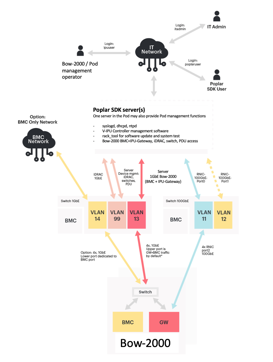
Fig. 4.2 Bow Pod64 system network overview
Option: VLAN 14 and the cabling to the dedicated BMC port can be provided as an upgrade for customers that want an isolated BMC network. This separates the BMC and IPU-Gateway traffic inside the Bow-2000 onto the two ports - BMC on the lower port and IPU-Gateway on the upper port. With this option enabled, VLAN 13 becomes an IPU-Gateway only VLAN. Please contact Graphcore Sales for more information.
4.2.2. Bow Pod64 system network interfaces
Port |
Role |
Speed |
IP address |
Config from |
VLAN (see note) |
|---|---|---|---|---|---|
Bow-2000: BMC |
BMC only management (future) |
1GbE |
10.1.1.1-16/22 |
Static DHCP |
14 |
Bow-2000: IPU-Gateway |
BMC+IPU-Gateway management |
1GbE |
10.1.2.1-16/22 |
Static DHCP |
13 |
Server: Port1 |
Mgmt Bow-2000 |
1GbE |
10.1.3.101/22 |
Local Netplan file |
13 |
Server: Port2 |
Div management iDRAC, switches & PDUs |
1GbE |
10.1.6.1/22 |
Local Netplan file |
99 |
Server: iDRAC |
Server BMC |
1GbE |
10.1.6.4-7/22 |
Manual setup |
99 |
Server: RNIC/Port0 |
RDMA Bow-2000 |
100GbE |
10.1.5.101/23 |
Local Netplan file |
11 |
Server: RNIC/Port1 |
RDMA NAS |
100GbE |
Site specific |
Site specific |
Site specific |
48x 1GbE + (4x 10G) Switch management port |
CLI + Switch BMC management |
1GbE |
10.1.6.2/22 |
Manual setup |
99 |
32x 100GbE + (4x 10G) switch management port |
CLI + Switch BMC management |
1GbE |
10.1.6.3/22 |
Manual setup |
99 |
PDU |
Power dist. unit |
1GbE |
10.1.6.8-11 |
Dynamic DHCP |
99 |
Note
Port based VLAN in switches (VLAN 13,14 and 99 in 1GbE switch, VLAN 11 in 100GbE switch)
4.2.3. Management switch configuration
Several VLANs need to be configured on the switches to separate traffic for the different hardware and integrate DHCP properly on the system.
The default management switch is Arista DCS-7010T-48-F.
Up to 4 interfaces per rack for PDUs and switches management
Up to 4 interfaces per rack for server management interfaces
Up to 4 interfaces per rack for server facing BMCs and gateways
Up to 16 interfaces per rack for combined Bow-2000 Gateway and BMC
Up to 16 interfaces per rack for BMC only connection (future option)
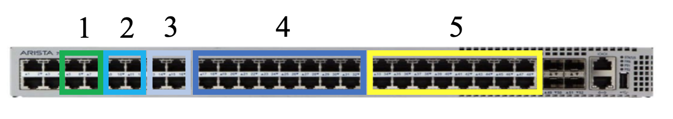
Fig. 4.3 Management switch VLAN assignments
These port groups are members of the switch’s internal port based VLANs. The VLAN assignments are given below.
VLAN 13: Bow-2000 BMC and IPU-Gateway traffic
VLAN 14: Bow-2000 BMC only traffic (option)
VLAN 99: Device management
Device management is intended for switch management, PDU remote management and any other device in the system with remote management interfaces.
The reference configuration for the management switch is given in Table 4.13.
Port |
Description |
Vlan |
Options |
|---|---|---|---|
Hostname MGMT-Switch |
|||
Switchport default mode access |
|||
Spanning-tree mode mstp |
|||
No aaa root |
|||
No ip routing |
|||
1 |
Datacentre BMC |
13 |
no snmp trap link-status |
2 |
Datacentre IPU-Gateway |
14 |
no snmp trap link-status |
3 |
Datacentre management |
99 |
no snmp trap link-status |
4 |
– |
– |
shutdown |
5-6 |
PDU management |
99 |
no snmp trap link-status |
7 |
ToR switch management |
99 |
no snmp trap link-status |
8 |
Server 1 Pod management |
99 |
no snmp trap link-status |
9-12 |
Servers BMC - iDRAC |
99 |
no snmp trap link-status |
13-16 |
Servers 1Gbe traffic |
13 |
no snmp trap link-status |
17-32 |
IPU IPU-Gateway and BMC |
13 |
no snmp trap link-status |
33-48 |
IPU BMC Only |
14 |
shutdown |
An example switch configuration file can be provided – please contact Graphcore support for details. This configuration file can be applied using one of the standard methods described by the switch manufacturer.
4.2.4. ToR switch configuration
The default ToR switch is an Arista DCS-7060CX-32S-F. The ports are allocated as follows:
One port per server for traffic between the server(s) and Bow-2000s, on VLAN11
One port per server for uplink traffic from the server(s) to datacentre network-attached storage. This is disabled in the default setup file since NAS configuration will be site specific.
16 ports for connection to the Bow-2000s on VLAN 11
This is disabled in the default setup file since the uplink configuration will be site specific.
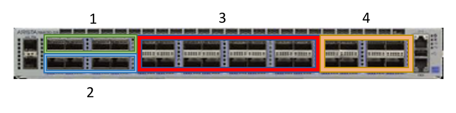
Fig. 4.4 ToR switch VLAN assignments
The reference configuration for the ToR switch is given in Table 4.14.
Port |
Description |
Vlan |
Options |
|---|---|---|---|
Hostname MGMT-Switch |
|||
Switchport default mode access |
|||
Spanning-tree mode mstp |
|||
No aaa root |
|||
lldp run |
|||
No ip routing |
|||
1/1 3/1 5/1 7/1 |
Server Uplink |
12 |
dcbx mode ieee priority-flow-control on priority-flow-control priority [0-7] no-drop no snmp trap link-status |
2/1 4/1 6/1 8/1 |
Server IPUoF |
11 |
dcbx mode ieee priority-flow-control on priority-flow-control priority [0-7] no-drop no snmp trap link-status |
9/1 to 24/1 |
Bow-2000 |
11 |
dcbx mode ieee priority-flow-control on priority-flow-control priority [0-7] no-drop no snmp trap link-status |
25/1 to 32/1 |
Datacentre Uplink |
See note |
dcbx mode ieee priority-flow-control on priority-flow-control priority [0-7] no-drop no snmp trap link-status |
Note
The VLAN assignment for the datacentre uplink ports will be site and configuration specific. In the default configuration file these ports are disabled.
A switch configuration file can be provided – please contact Graphcore support for details. This configuration file can be applied using one of the standard methods described by the switch manufacturer.
4.2.5. Bow Pod64 VLAN assignments
Each switch is configured independently based on the number of interfaces needed for the Pod size (in this case Bow Pod64). This section describes the interfaces used in a Bow Pod64 system with figures showing interface allocation.
Fig. 4.5 shows the VLAN assignments for the server connecting between the server(s) and the switches. Four server-facing ports are shown for each group on the switches to allow for up to 4 servers in the Bow Pod64 system.
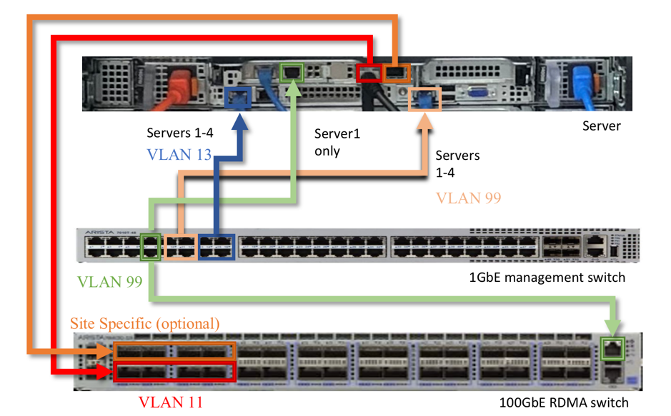
Fig. 4.5 Dell R6525 server VLAN connectivity
Fig. 4.6 shows the VLAN assignments for the Bow-2000s connecting to the switches.
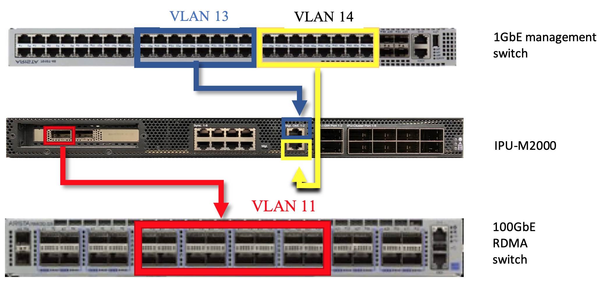
Fig. 4.6 Bow-2000 server VLAN connectivity
4.2.6. Server network configuration
We recommended using the Netplan network manager to configure the server using Netplan configuration files.
Two 1GbE baseT connections are required to the 1GbE management switch for Server 1. Only one 1GbE baseT connection is required to the 1GbE management switch for additional servers. Fixed IP addresses are required.
One 100GbE connection is required to the 100GbE switch. A fixed IP address is required.
The default RNIC MTU size (1500 bytes) is used for the 100GbE network interface on the host so this does not need to be specified in the Netplan configuration file.
Subnets for each interface should be capable to contain the number of devices of the installation.
Example Netplan configuration file
The default location for this file is
/etc/netplan/01-netcfg.yaml.In this example:
Interface eno3 is facing the 1GbE network with Bow-2000 BMCs and gateways
Interface eno4 is facing the user’s network
Interface enp59s0f1 is facing the Bow-2000 100GbE RNICs
network:
  version: 2
  renderer: networkd
  ethernets:
    eno1np0:
      dhcp4: yes
    eno2np1:
      dhcp4: yes
    eno3:
      addresses:
        - 10.1.3.101/22
    eno4:
      dhcp4: yes
    enp59s0f0:
      dhcp4: yes
    enp59s0f1:
      addresses:
        - 10.1.5.101/23