7. IPU-POD128 installation
An IPU‑POD128 system consists of two IPU‑POD64 logical racks with optical GW-Link cables cross connected between them. Table 7.1 shows the BOM for an IPU‑POD128.
Item |
Product number |
Description |
Quantity |
1 |
900-0020 |
IPU-POD64 Logical Rack |
2 |
2 |
SM-ULC-DX-PVC-1.5M |
1.5m LC UPC to LC UPC Duplex OS2 Optical Cable for GW-Links |
32 |
3 |
TR-ZC13H-N00 |
100Gb/s QSFP28 DR Single Lambda Optical Transceiver for GW-Links |
64 |
Fig. 7.1 shows the IPU‑POD128 layout and cross connected GW-Link cables between the two IPU‑POD64 racks.
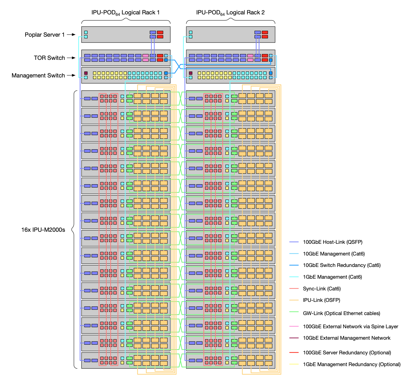
Fig. 7.1 IPU‑POD128 topology with cross connected GW-links
Fig. 7.2 shows the location of the GW-Link ports on the front of each IPU-M2000.
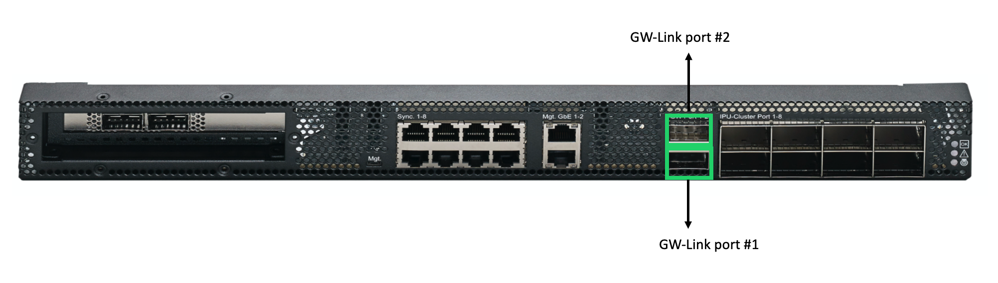
Fig. 7.2 IPU-M2000 front panel showing GW-Link ports
Table 7.2 gives the IPU-M2000 GW-Link port mappings between the two IPU‑POD64 racks, with the GW-Links cross connected:
GW-Link port 1 of each IPU-M2000 in the left-hand IPU‑POD64 connects to GW-Link port 2 of the matching IPU-M2000 (same rack index) in the right-hand IPU‑POD64.
GW-Link port 2 of each IPU-M2000 in the left-hand IPU‑POD64 connects to GW-Link port 1 of the matching IPU-M2000 (same rack index) in the right-hand IPU‑POD64.
From left-hand IPU-POD64 |
To right-hand IPU-POD64 |
|---|---|
IPU-M2000 #16 GW-Link ports 1,2 |
IPU-M2000 #16 GW-Link ports 2,1 |
IPU-M2000 #15 GW-Link ports 1,2 |
IPU-M2000 #15 GW-Link ports 2,1 |
IPU-M2000 #14 GW-Link ports 1,2 |
IPU-M2000 #14 GW-Link ports 2,1 |
IPU-M2000 #13 GW-Link ports 1,2 |
IPU-M2000 #13 GW-Link ports 2,1 |
IPU-M2000 #12 GW-Link ports 1,2 |
IPU-M2000 #12 GW-Link ports 2,1 |
IPU-M2000 #11 GW-Link ports 1,2 |
IPU-M2000 #11 GW-Link ports 2,1 |
IPU-M2000 #10 GW-Link ports 1,2 |
IPU-M2000 #10 GW-Link ports 2,1 |
IPU-M2000 #9 GW-Link ports 1,2 |
IPU-M2000 #9 GW-Link ports 2,1 |
IPU-M2000 #8 GW-Link ports 1,2 |
IPU-M2000 #8 GW-Link ports 2,1 |
IPU-M2000 #7 GW-Link ports 1,2 |
IPU-M2000 #7 GW-Link ports 2,1 |
IPU-M2000 #6 GW-Link ports 1,2 |
IPU-M2000 #6 GW-Link ports 2,1 |
IPU-M2000 #5 GW-Link ports 1,2 |
IPU-M2000 #5 GW-Link ports 2,1 |
IPU-M2000 #4 GW-Link ports 1,2 |
IPU-M2000 #4 GW-Link ports 2,1 |
IPU-M2000 #3 GW-Link ports 1,2 |
IPU-M2000 #3 GW-Link ports 2,1 |
IPU-M2000 #2 GW-Link ports 1,2 |
IPU-M2000 #2 GW-Link ports 2,1 |
IPU-M2000 #1 GW-Link ports 1,2 |
IPU-M2000 #1 GW-Link ports 2,1 |