Note: Searching from the top-level index page will search all documents. Searching from a specific document will search only that document.
Find an exact phrase: Wrap your search phrase in "" (double quotes) to only get results where the phrase is exactly matched. For example "PyTorch for the IPU" or "replicated tensor sharding"
Prefix query: Add an * (asterisk) at the end of any word to indicate a prefix query. This will return results containing all words with the specific prefix. For example tensor*
Fuzzy search: Use ~N (tilde followed by a number) at the end of any word for a fuzzy search. This will return results that are similar to the search word. N specifies the “edit distance” (fuzziness) of the match. For example Polibs~1
Words close to each other:~N (tilde followed by a number) after a phrase (in quotes) returns results where the words are close to each other. N is the maximum number of positions allowed between matching words. For example "ipu version"~2
Logical operators. You can use the following logical operators in a search:
+ signifies AND operation
| signifies OR operation
- negates a single word or phrase (returns results without that word or phrase)
Note the correct orientation of the IPU-M2000, server and switch units in the rack to ensure correct airflow.
The front interface of the IPU-M2000 units (connectivity ports) should be matched with the front door of the rack (cold aisle). The rear interface of the server and switches (power and fans) should be matched with the rear door of the rack (hot aisle).
Note
You can click on any of the images below to view them full size
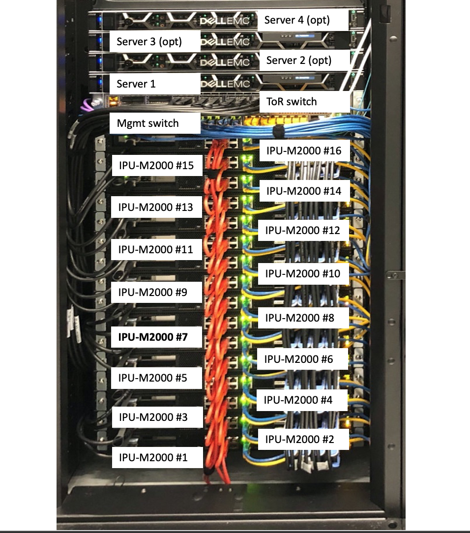
Note that Fig. 3.1 shows a four-server version of the IPU‑POD64.
The default reference design has one server which would be the server in the lowest position, closest to the switches.
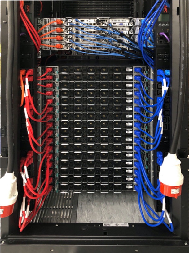
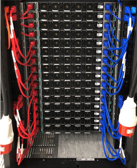
Fig. 3.2 Completed rack: hot aisle (four-server version)
Note that Fig. 3.2 shows three blue RJ45 cables in each R6525 server. In the default build, servers 2 to 4 only have two blue RJ45 cables. See Section 3.6.7, Dell R6525 server(s) cabling for more information about server cabling.
Note also that Fig. 3.2 shows a four-server version of the IPU‑POD64.
The default reference design has one server which would be the server in the lowest position, closest to the switches.
Ideally you should reference this document from a tablet device to allow you to zoom in on photographs. If you reproduce this document on paper it should be done in colour otherwise you will not be able to see cable colours and other notations properly.
The IPU-M2000 mounting system requires a rail-to-rail distance of 720mm. This document describes the adjustments required for an AR3300SP rack. If using a different rack this rail distance must be observed.
Follow the instructions to remove the outer packaging of the APC AR3300SP rack, ensuring that you safely store these materials for later repackaging. Do not remove the rack from the shock pallet.
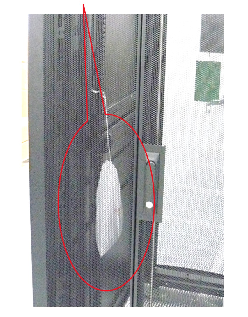
Remove the white bag (Fig. 3.3) from the rack. This contains screws and cage nuts to be used in the assembly of the components into the rack.
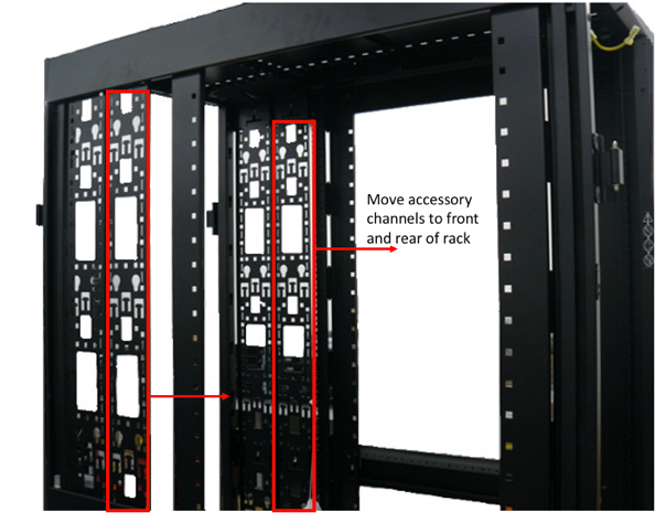
Remove the top and bottom side panels. The vertical accessory channels should be positioned at the very front and very rear of the rack. If necessary, move these from their shipping positions (Fig. 3.5).
Set the rear accessory channel to the furthest position in the rack.
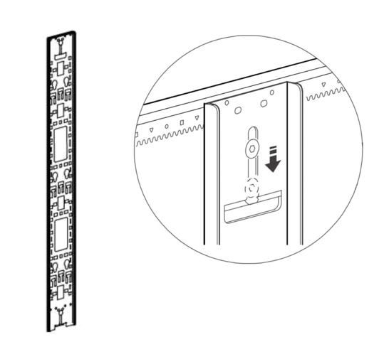
Tighten up the screws ensuring the teeth engage into the slots in the rail, as shown in Fig. 3.7.
Fig. 3.7 Rear accessory channel (ensure teeth engage in slots)
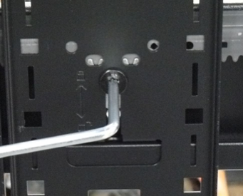
Using a Torx TX30 screwdriver, make both rear vertical rack rails loose and freely movable.
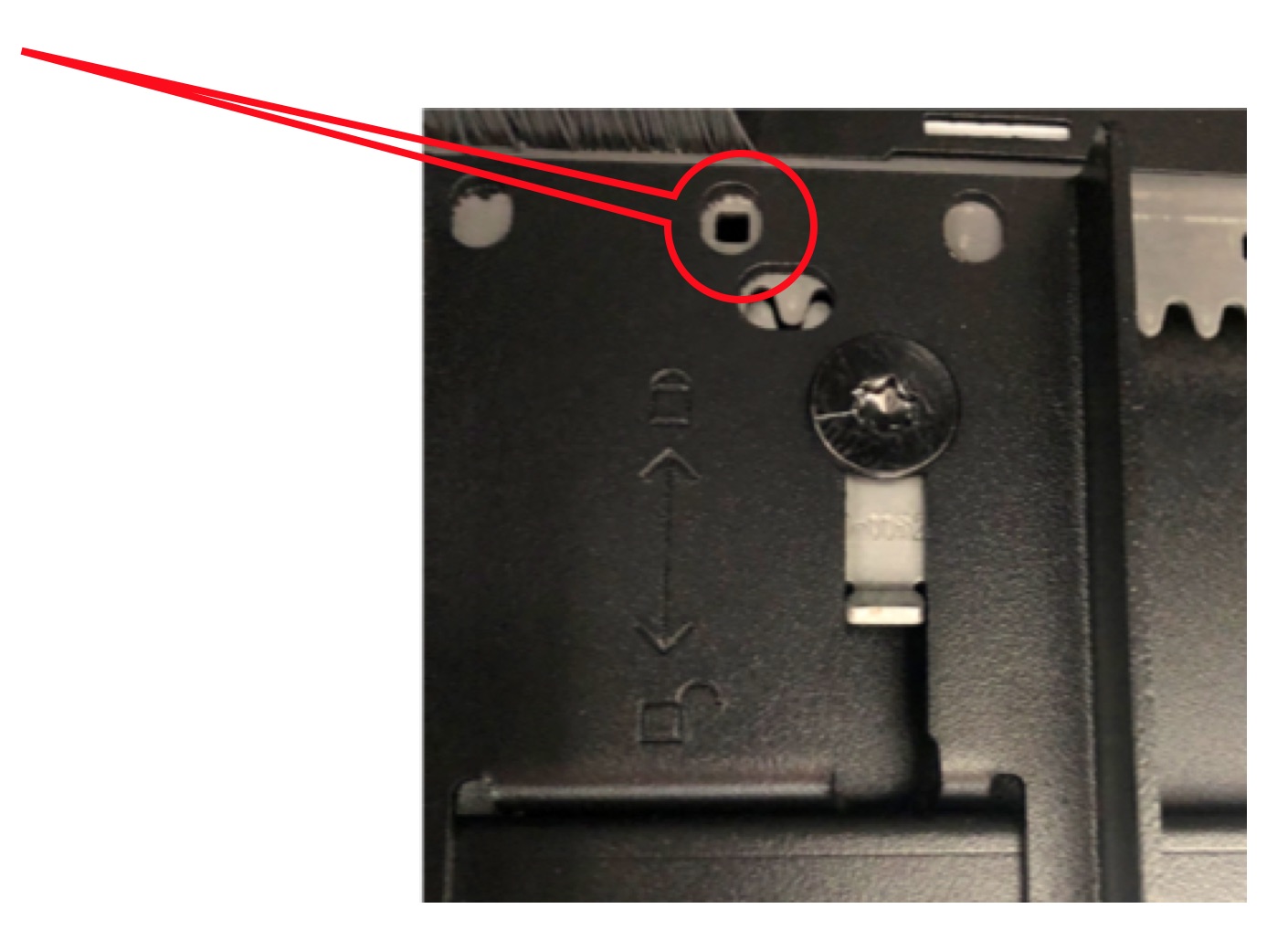
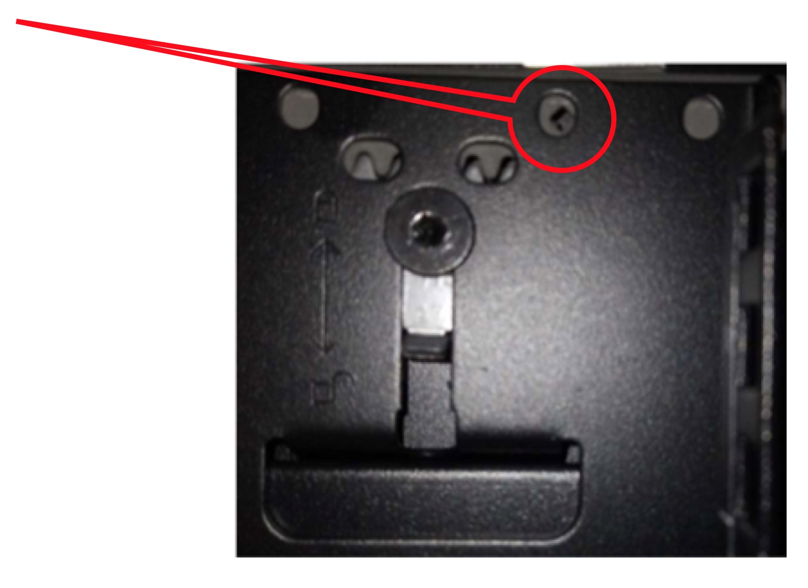
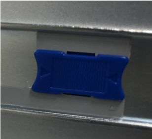
Position the rear vertical rack rails such that there is 20mm of distance between the rear face of the vertical rack rail and the racks rear frame. This should result in a square symbol being visible through the alignment window at the top and bottom of the rail, as shown in Fig. 3.8.
Secure the rail into position by moving the TX30 screws back upwards such that the teeth engage with both the supporting rails. This must be done at the top and bottom of the bracket.
Using a Torx TX30 screwdriver, make both front vertical rack rails loose and freely movable.
Install the accessory channels in the front of the rack (one on the left hand side, one on the right hand side) at the frontmost position possible, moving the TX30 screws back upwards such that the teeth engage with both the supporting rails. This must be done at the top and bottom of the bracket.
Note
To ensure the clips on the accessory channels align with the channel in the rack, lift the accessory channels through the cut-out in the top of the rack and then drop them down onto the channels.
Move the vertical rack rails tight against the vertical cable organisers such that only a single diamond symbol is visible through the alignment window at the top and bottom of the rail, see Fig. 3.9.
Secure the rail into position by moving the TX30 screws back upwards such that the teeth engage with both the supporting rails. This must be done at the top and bottom of the bracket.
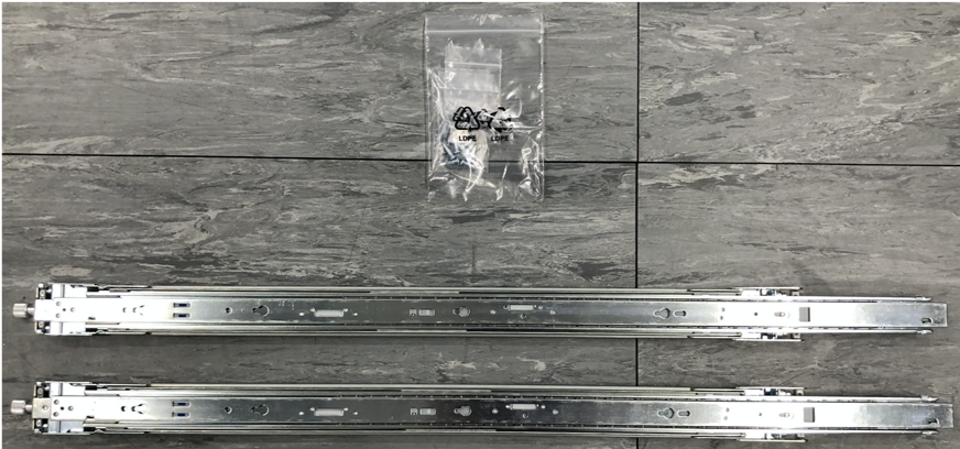
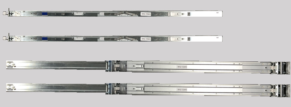
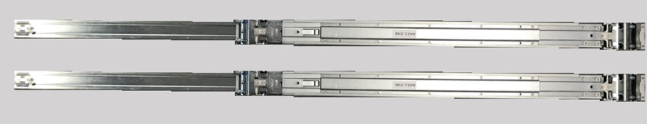
The IPU-M2000 rail kit comprises two mated inner and outer rack rails and an accessory bag containing screws. The inner rail affixes to the body of the IPU-M2000 and the outer rail affixes to the vertical rack rails in the server cabinet.
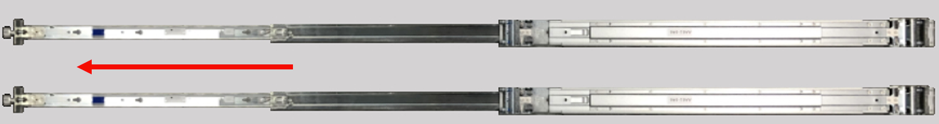
Firstly, separate the mated inner and outer rails:
Fully extend the rails by pulling on the end which has the captive thumb screw attached (Fig. 3.11):
Mate the inner rails (the thinner of the two separated rails which has a captive thumb screw at one end) to the body of the IPU-M2000. Note that the inner rails are mirrored and are not handed. As such, the procedure for inner rail fixing is the same for the left and right hand inner rails.
The inner rail should be oriented such that the captive thumb screw end is at the end of the IPU-M2000 containing the network ports.
To affix the inner rail to the body of the IPU-M2000:
Offer up the inner rail to the side of the IPU-M2000 and ensure that all fixing pins are sitting within the enlarged opening of the retention channel (Fig. 3.14):
Push the inner rail towards the end of the IPU-M2000 containing the network ports, you should hear a click as the latching mechanism locks behind the head of a fixing pin (Fig. 3.15):
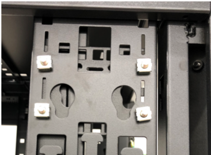
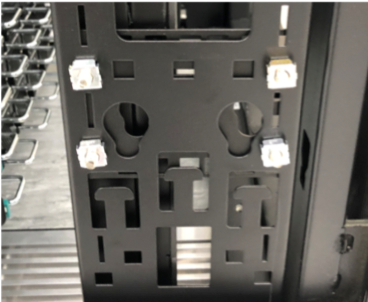
Screw the PDU support brackets to the inside of the cabinet.
The PDU brackets should be installed at the rear of the rack: one bracket on top with 9cm distance from the top of rack and one bracket on the bottom with 12cm distance from the bottom of rack. Fig. 3.21 illustrates this. Follow the PDU bracket installation instructions.
Earlier in the guide we affixed the inner rack rails to the IPU-M2000 body. The next step in installing the IPU-M2000s is to install the outer rack rails into the rack.
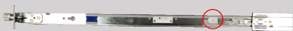
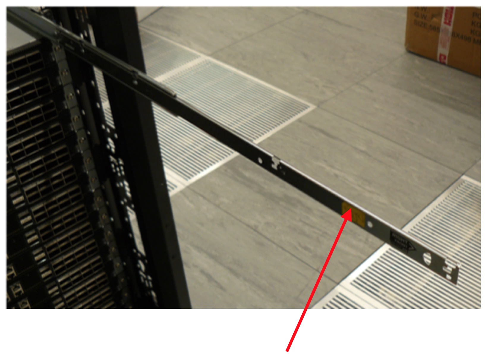
It is possible to identify the front and rear of the outer rail by finding the large metal latching mechanism. This is to be located at the rear of the rack. The outer rail is also embossed with the text “FRONT” at the front end of the rail.
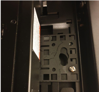
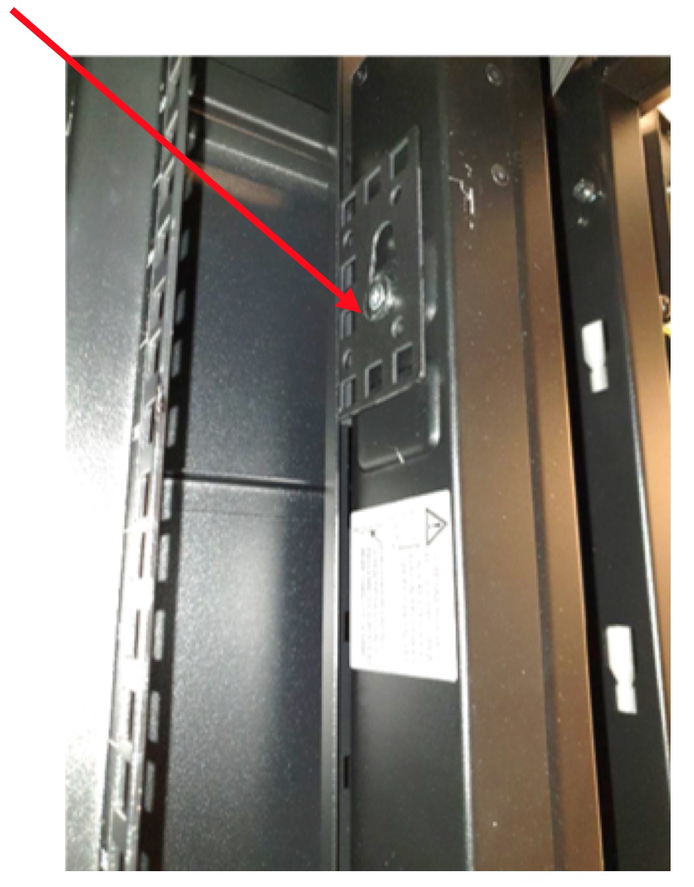
The outer rail large metal latch end is to be installed at the rear of the rack, as shown in Fig. 3.22.
Fig. 3.22 Attachment point for IPU-M2000 outer rail
For each rack U in U1 through U16 (inclusive), perform the steps below with both the left hand and right hand outer rack rails:
Pull on each end of the outer rail to adjust the rail length to suite your rack
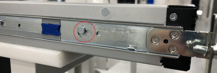
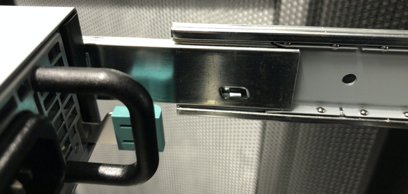
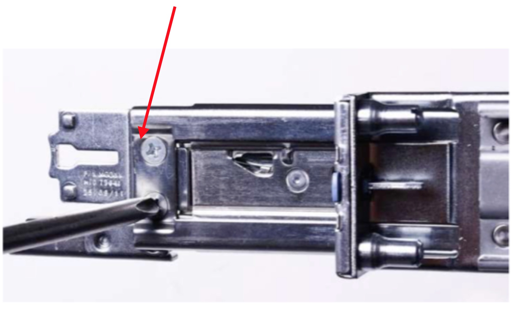
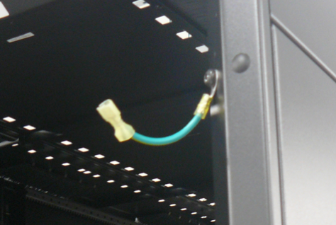
Locate the front end of the outer rail and hold it behind the square holes in the vertical rack rail for your installation U. Pull the outer rail towards the vertical rack rail and the latching mechanism will click and hold the outer rail in place (Fig. 3.23):
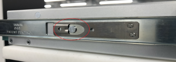
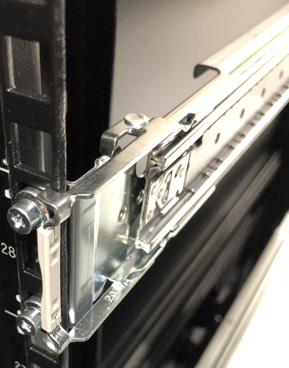
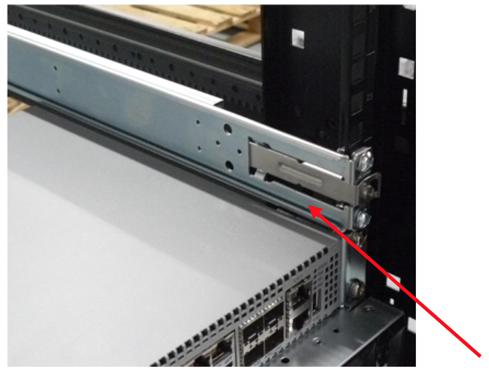
Locate the rear end of the outer rail and slightly open the large metal latch, then press the upper and lower locating pins into the square holes in the vertical rack rail. Release the large metal latch and the outer rail will now be secured to the vertical rack rail (Fig. 3.24):
Fig. 3.24 IPU-M2000 outer rail secured to vertical rack rail
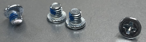
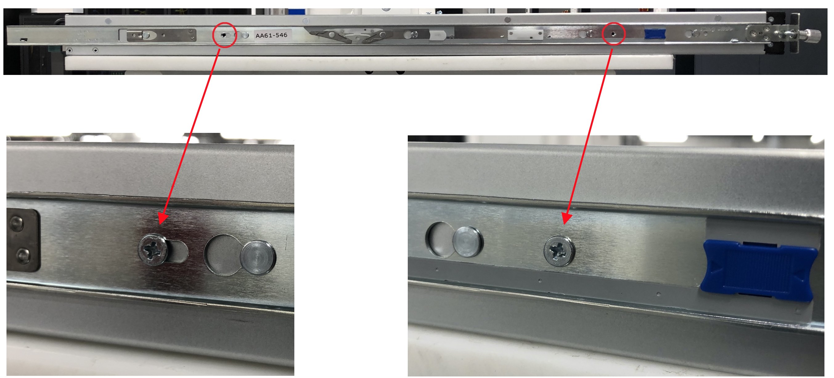
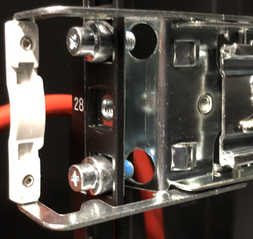
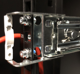
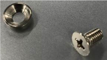
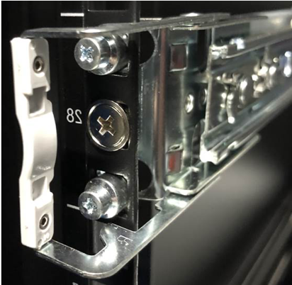
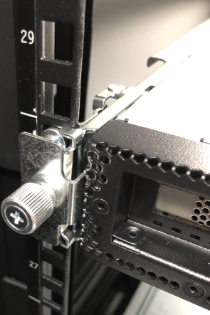
Included in the rack rail accessory bag are two screws and two washers. One screw with one washer should be screwed through the vertical rack rail and into the outer rack rail threaded hole. The washer should be used in such a way that the washer sits flush with the head of the screw –like a cup. The screws and how they fit are shown in Fig. 3.25 and Fig. 3.26.
This should be repeated for both outer rack rails.
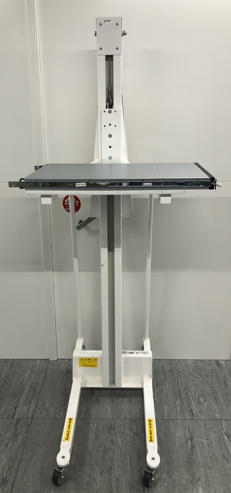
Place the IPU-M2000 onto an appropriate server lift and adjust the height such that it is suitable for the sliders (Fig. 3.28). If a lift is not available, this is a two person operation.
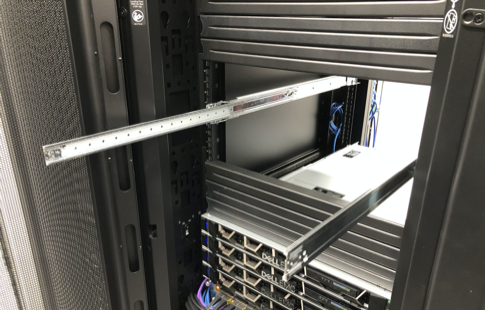
Slide the protruding inner rails into the receiving channel of the extended outer rails (Fig. 3.29):
Fig. 3.29 Slide IPU-M2000 inner rails into outer rails
Whilst the server lift is supporting the full weight of the IPU-M2000, slide the IPU-M2000 into the extended outer rails until you feel both sides engage a stopping mechanism (Fig. 3.30).
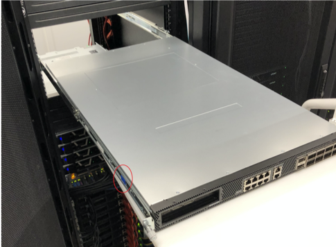
Simultaneously pull on the blue tabs for the release mechanism at each side of the IPU-M2000 and then push the IPU-M2000 unit fully into the rack (Fig. 3.31):
Fit the sliders for the ToR switch into position 18 on the rack ensuring both ends of the slider are pushed firmly into the mounting slots on the rack rail (Fig. 3.34).
Install the two PDUs vertically at the rear of the rack, one on the left side and one on the right side. Push the mains cable through the roof of the rack and then clip the PDUs onto the PDU bracket as shown in Fig. 3.35:
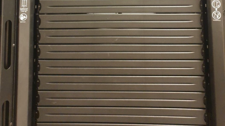
Remove and discard the cable management arm brackets from the rear of each tool-less sliding rail (Fig. 3.36).
Fig. 3.36 Cable management arm brackets - to be removed
Install the tool-less sliding rail kit(s). The reference design has a single server installed in rack slot #19; in four server configurations they are installed in rack slots #19-#22.
Pull out the rail and fit the server to the rail ensuring the T pins on the side of the server locate in the slots on the rail. Ensure that the power supplies on the server face the rear of the rack (Fig. 3.37).
Fig. 3.37 Sliding rail kit for server installation
Note
Use an appropriate server lift or have two people installing the servers to ensure correct fitting
Push the server gently from the front to lock it into the slides then press the tab on the side of the slides and push the server fully home in the rack. Repeat the above process for each server if installing multiple servers.
Remove the Velcro tape from the light pipes on the rear of the servers.
Remove the small plastic tab on the left front side of the server bezel and clip the bezel in place on the front of the server ensuring the connection pins on the right hand side of the bezel line up with the connector on the server, as shown in Fig. 3.38.
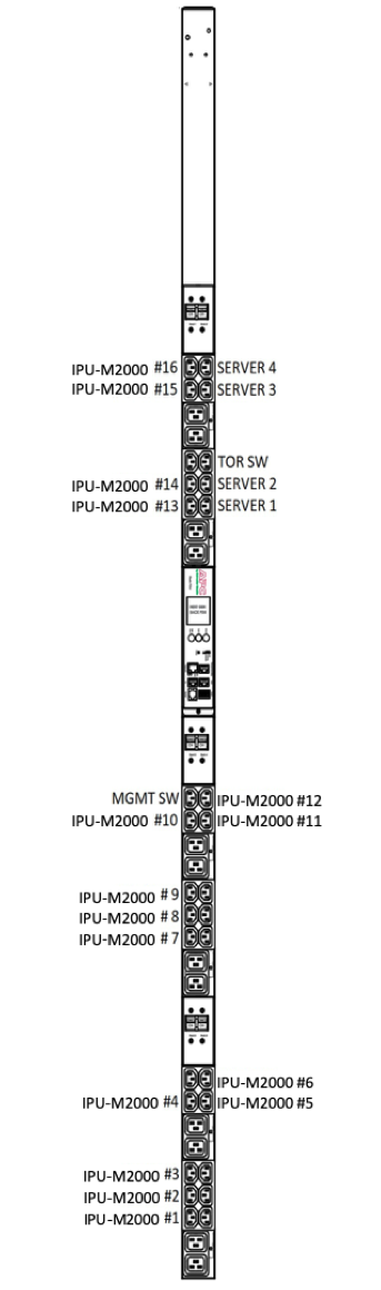
The following sections detail the cabling of the rack and the dressing of the cables within the rack. For reference, the IPU-M2000s and server(s) are numbered as shown in Fig. 3.39:
3.6.1. IPU-M2000 to IPU-M2000 IPU-Link connectivity (OSFP)
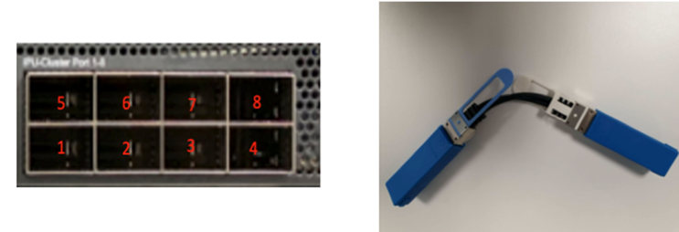
There are eight OSFP IPU-Link ports on the right side of each IPU-M2000. Using the supplied 60x 0.3M OSFP cables, and starting at IPU-M2000 #1 (bottom-most IPU-M2000 in the rack), link the top row of four ports (5-8) to the bottom row of four ports (1-4) in the IPU-M2000 that is installed directly above (see Fig. 3.40 and Table 3.2 below). This applies to all IPU-M2000s except for the top row (5-8) of the top-most IPU-M2000 (#16) and the bottom row (1-4) of the bottom-most IPU-M2000 (#1), which are connected together using the 1m OSFP cables.
Fig. 3.40 IPU-M2000 IPU-Link port numbering and IPU-Link cables
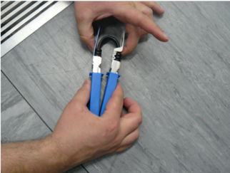
Before attempting to install the OSFP cables, it is beneficial to manipulate the cable to form a tight loop (Fig. 3.41). During manufacture and shipping, the cables can form quite a stiff shape, so manipulating the cables before installing them reduces stresses on the socket during install.
Using the 0.15m red Ethernet RJ45 cable, wire the 16 IPU-M2000s as follows:
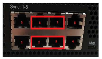
Starting from IPU-M2000 #1 at the bottom of the rack, insert one side of a cable into port 6 and one side of another cable into port 7.
Insert the other side of the cable from port 6 of IPU-M2000 #1 into port 2 of IPU-M2000 #2, and the other side of the cable from port 7 of IPU-M2000 #1 into port 3 of IPU-M2000 #2.
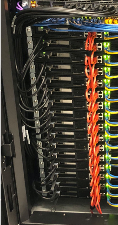
Continue the cabling for all IPU-M2000s. When completed the top row (6,7) of the top-most IPU-M2000 (#16) connectors should be connected to the bottom row (2,3) of the bottom-most IPU-M2000 (#1) connectors with 1m red Ethernet RJ45 cables.
Fig. 3.45 shows the final IPU-M2000 in-rack Sync-Link cabling.
Fig. 3.45 Final IPU-M2000 in-rack Sync-Link cabling
Table 3.3 gives the IPU-M2000 Sync-Link port mapping.
3.6.3. IPU-M2000 to management switch cabling (RJ45)
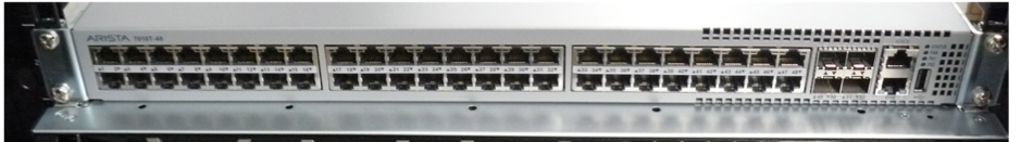
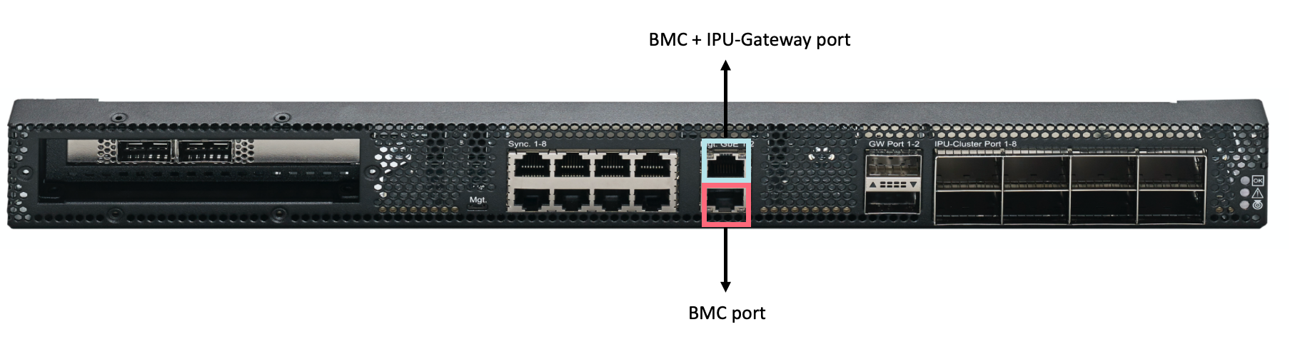
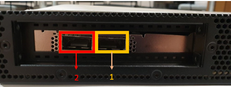
There are two Ethernet ports in the middle of each IPU-M2000 (see Fig. 3.46). One of them is a BMC + IPU-Gateway port (upper port) and the other is a BMC port (lower port).
Start cabling using a 1.0m yellow cable and insert one end into port 48 of the management switch.
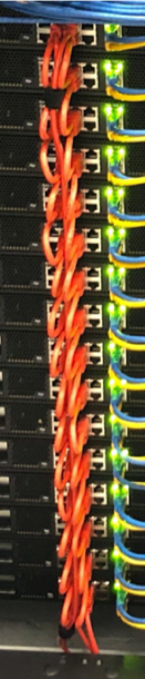
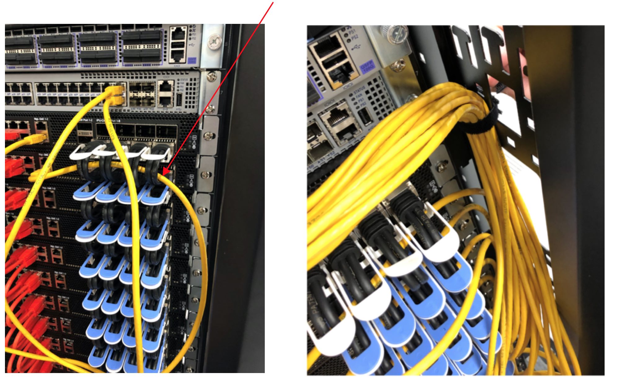
Run the cable through the loop in the OSFP connector as shown in the left hand picture in Fig. 3.48 and connect it to the BMC port on IPU-M2000 #16 (top IPU-M2000 in the rack).
Repeat the process for ports 47 to 37 using 1.0m yellow cables and ports 33 to 36 using 1.5m cables.
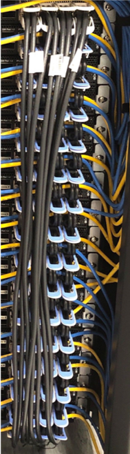
When all cables have been connected, dress the loom down the side of the cabinet and secure the bundle with a Velcro strip as shown in the right hand picture in Fig. 3.48.
The port mapping between the management switch and the IPU-M2000 BMC sockets is given in Table 3.5.
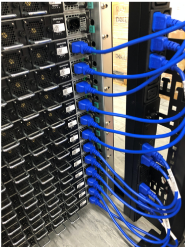
Start cabling using a 1.0m blue RJ45 cable and insert one end into port 32 of the management switch.
Run the cable through the loop in the OSFP connector as shown in the left hand picture in Fig. 3.49 and connect it to the BMC+IPU-Gateway port on IPU-M2000 #16.
Repeat the process for ports 31 to 25 using 1.0m blue cables, and ports 24 to 17 using 1.5m blue cables. When all cables have been connected, dress the loom down the side of the cabinet and secure the bundle with a Velcro strip, as shown in the right hand picture in Fig. 3.49.
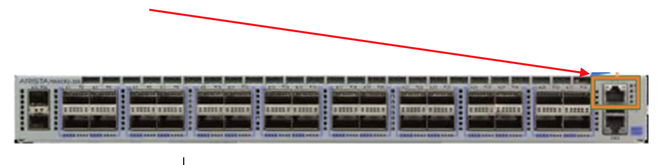
Using a 1.0m blue cable, connect port 7 of the management switch to the top RJ45 connector on the ToR Switch (Fig. 3.50).
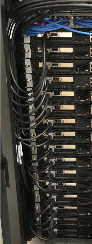
The next step is to connect the IPU-M2000s to the ToR switch. There are two RNIC ports on the left side of each IPU-M2000, as shown in Fig. 3.51. Only one of them should be connected from each IPU-M2000 to the ToR switch with either the 1m or 1.5m QSFP cables supplied.
In order to manage the cables, the QSFP cables are divided into two different lengths:
8x QSFP 1.0m from IPU-M2000 #9-16 to ToR switch ports 16 to 9
8x QSFP1.5m from IPU-M2000 #1-8 to ToR switch ports 17 to 24
Start from port 9 on the ToR switch and connect the cable to port 2 of IPU-M2000 #16.
Continue cabling from ports 10 to 24 on the ToR switch to port 2 on IPU-M2000 #15 to IPU-M2000 #1 respectively.
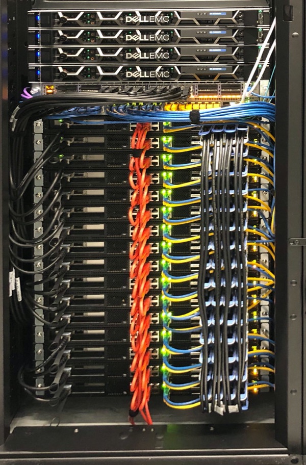
Dress the cables down the side of the cabinet. A set of four cables can be looped into cut-outs on the side of the cabinet. Tie the bundle together at the top with a Velcro strip as shown in Fig. 3.52.
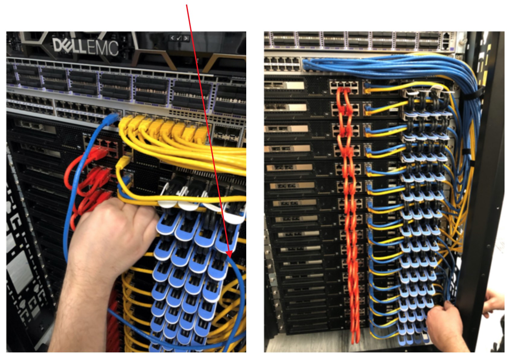
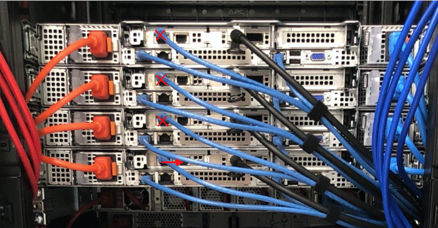
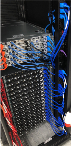
All cables should be routed from the rear of the server to the right-hand side when viewed from the rear (see Fig. 3.54), then along the side of the rack using the cable management holes in the vertical rack rails.
Note that Fig. 3.54 shows the four-server version. The default build has one server (the one in the lowest position).
Note
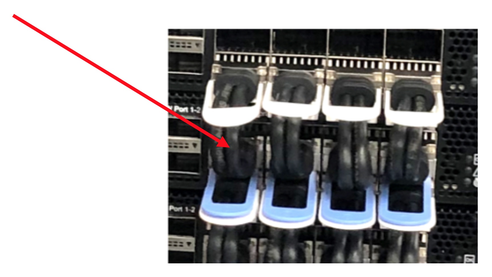
Picture to be updated: Fig. 3.54 shows three blue RJ45 cables in each R6525 server. In the default build, servers 2 to 4 only have two blue RJ45 cables. The cables removed in the default build are marked with a red cross. The additional cable in server 1 moves to the port on the right, as indicated by the red arrow.
ToR switch ports 8 and 7 connect to the bottom server (server 1). Therefore, if you are only using 1 server then only ports 8 and 7 of the ToR switch are used.
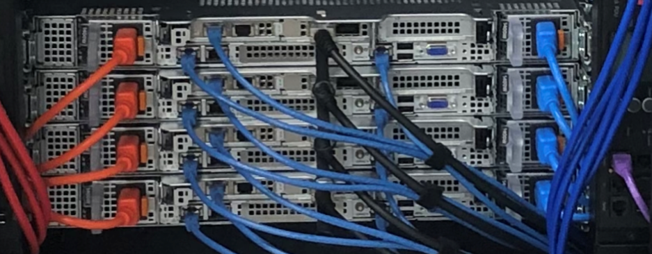
The final ToR switch to server cabling is shown in Fig. 3.56 for a four server version.
Fig. 3.56 ToR switch to server cabling: cable connections (4 server version)
Note
The figures in this section only show one black 1.5m QSFP cable per server. In a normal installation there would be two black 1.5m QSFP cables per server.
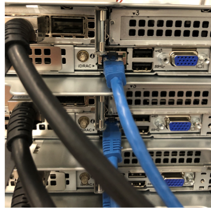
3.6.9. Management switch to Dell server(s): iDRAC
Using four of the 1.5m blue RJ45 cables connect the management switch to the Dell server(s) as follows:
Ports 9 to 12 on the management switch connect to the iDRAC connector on the server(s) - Fig. 3.57.
Port 9 is connected to the bottom server (server 1). If you only have one server then only port 9 on the management switch is used.
Fig. 3.57 Management switch to server cabling: iDRAC for 4 server version
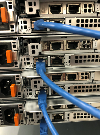
3.6.10. Management switch to Dell server(s): network connector
Using four of the 1.5m blue RJ45 cables connect the management switch to the Dell server(s) as follows:
Ports 13 to 16 on the management switch connect to the network connector on the server(s) - Fig. 3.58.
Port 13 is connected to the bottom server (server 1). If you only have one server then only port 13 on the management switch is used.
Fig. 3.58 Management switch to server cabling: network connector(s) for 4 server version
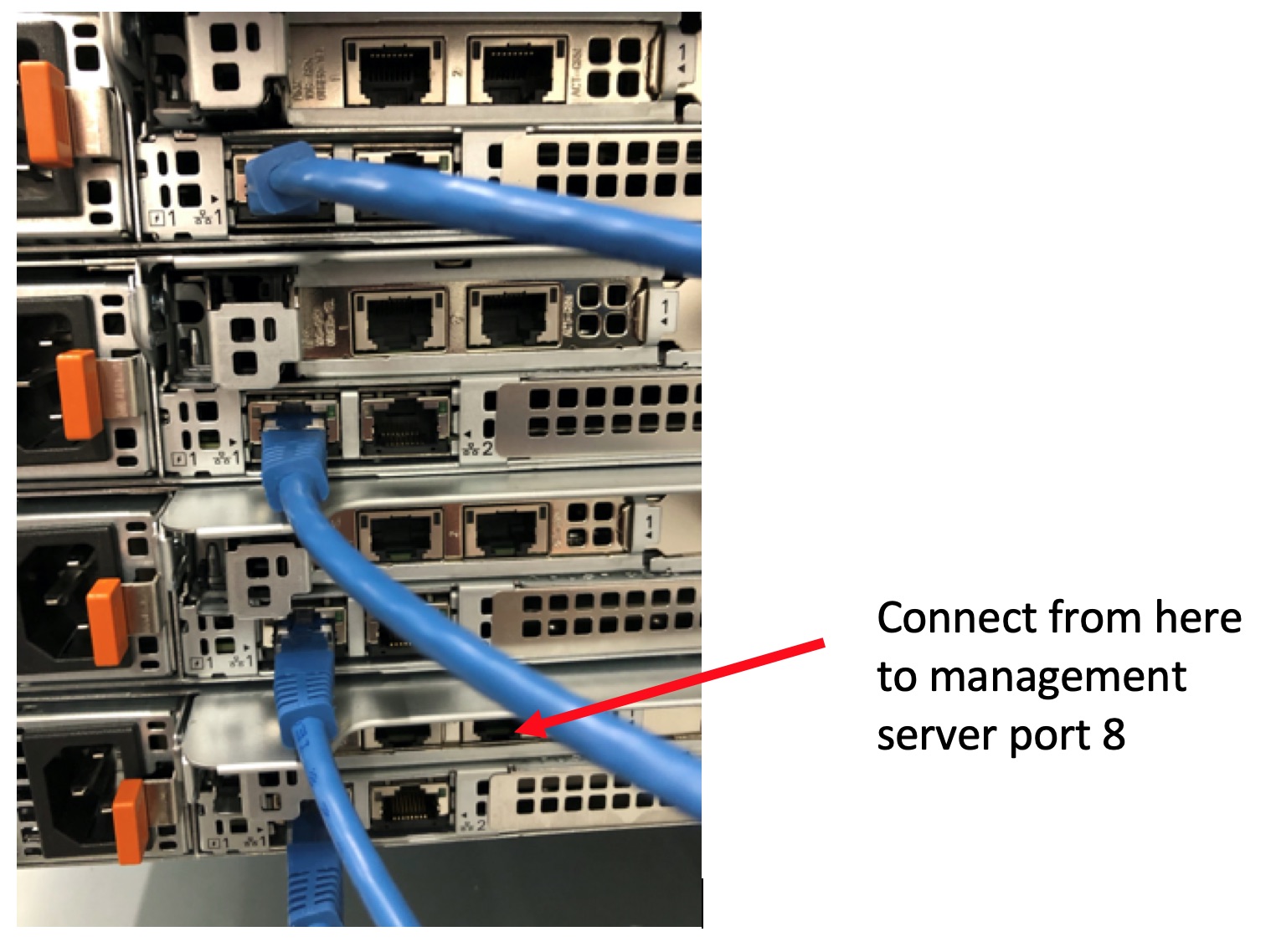
3.6.11. Management switch to Dell server(s): switch management
Using one of the 1.5m blue RJ45 cables connect the management switch to server 1 as follows:
Port 8 from the management server is connected to the lowest server (server 1) - the correct port to connect to on the server is shown in Fig. 3.59. This is used for control of the PDUs in the case where server 1 is used as the management server.
Fig. 3.59 Management switch to server cabling: switch management
Ethernet port on left side PDU | Management switch port 5
RJ45 2m
Ethernet port on right side PDU
Management switch port 6
RJ45 2m
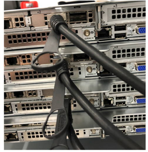
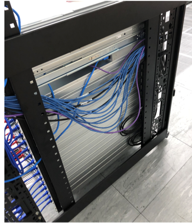
Allow all the cables going to the server to hang down in the rack as shown in Fig. 3.60. This allows the cables to be pulled slightly if it is necessary to remove them from a server.
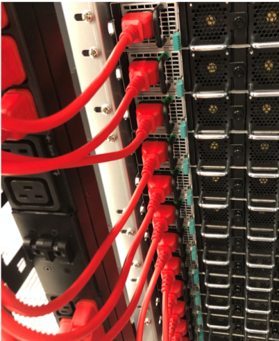
Start by cabling IPU-M2000 #1 using 0.5m power cables. Ensure that only three IPU-M2000s are connected to the same bank on the PDU. Red cables to the left PDU and blue cables to the right PDU (as seen looking at the rear of the rack).
Table 3.10 defines the power cable lengths for each IPU-M2000:
Using 1m C13 to C14 power cables (selecting the correct coloured cable to match the PDU colour), connect the server(s) to the PDUs as shown in Fig. 3.66.
The power plugs for the PDUs must not exit the top of the rack, they must stay inside the rack and be secured to the vertical mounting flanges. You need to ensure that there are no cables on the outside of the rack.
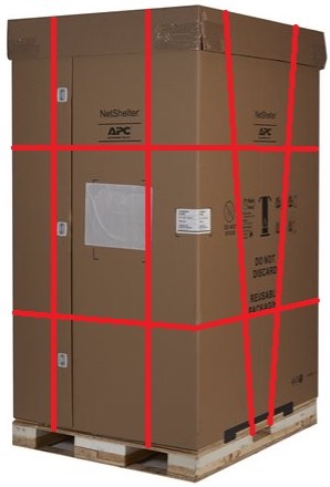
If you need to re-package the rack then follow the reverse of the steps taken when you unpacked the rack. It is important to ensure that the large clear plastic bag has no tears or holes and is refitted correctly as this bag provides protection from water ingress. It is also important that you ensure that the plastic bag containing the bolts is still affixed to the foam packaging. You also need to fit sufficient straps to secure the packaging – there should be a total of four vertical straps (two per 180 degrees) and two horizontal straps, as shown in Fig. 3.69.