3. Installation procedure
This procedure assumes a completely populated rack is provided to the data centre. Note that the IPU‑POD64 will arrive on a single pallet and forklift access will be required for handling.
Follow the instructions provided in the following steps, in the order they are given:
3.1. Unpack the rack
The complete IPU‑POD64 is provided on a pallet in the original rack packaging. Instructions for unpacking the APC AR3300SP rack can be found here.
Note that a forklift will be required for installation of a fully populated rack into a data centre.
3.2. Connect power and network to the rack
The power connections to the rack are two IEC 60309 32A 3-Phase + N + E connectors. The PDU whip length is 1.8 meters and the cable exits at the top of IPU‑POD64 rack. We recommended that the two inputs are connected to two diverse power trains because, within the rack, these are used for redundant supplies.
When both power connections are powered, a constant green LED on the two power supply units (next to the AC power inlet) on each IPU-M2000 (on the hot aisle/power inlet side) will indicate that both power units are operational.
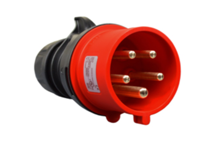
Fig. 3.1 IEC 60309 connector
The default IPU‑POD64 rack configuration contains two switches: a TOR data-plane switch and a management switch.
3.2.1. ToR data switch
The ToR data switch provided in the default IPU‑POD64 build is a 32 port 100GbE RoCE/RDMA switch (Arista DCS-7060CX-32S-F) located below the servers. See the IPU-POD64 Build and Test Guide for details on how this should be configured.
Ports 1 to 8 on this switch are reserved for uplink to the data centre network. A minimum of two 100Gbps uplinks are required and eight 100 Gbps uplinks are recommended. It is important that priority flow control (PFC) is enabled on the ToR switch and on the server(s).
3.2.2. Management switch
The management switch provided in the default IPU‑POD64 build is a 48 port 1GbE switch (Arista DCS-7010T-48-F) located below the ToR switch. See the IPU-POD64 Build and Test Guide <https://docs.graphcore.ai/projects/ipu-pod64-build-test/>`_ for details on how this should be configured. Ports 1-3 are reserved for uplink to the data centre network.
Port 1: Customer uplink for BMC + GW
Port 2: Customer uplink for BMC-only (optional upgrade)
Port 3: Customer management interface
3.3. Boot the system
Press the power button on the server front, and the server(s) should automatically boot. You are recommended, but not required, to attach a console to the management server (server 1 in the lowest position, if there is more than one server) to monitor the boot process. A constant green LED on the server front will indicate a successful boot.
Once the boot process is complete, each IPU-M2000 should indicate a successful boot state with a constant green LED on the cold aisle (connector side). After all the IPU-M2000s and server(s) have successfully booted, you need to log in to the management server so that all the IPU-POD software versions can be checked and updated. How to do this is explained in the next step, Section 3.4, Check the IPU-POD software versions.
3.4. Check the IPU-POD software versions
There are two main components of the IPU-POD software:
IPU-M2000 system software pack
Contains the system software for all the software components of the IPU-M2000s. Comes bundled with a tool for performing administrative tasks on all the IPU-M2000s.
V-IPU server
Used for partitioning the IPU‑POD64 into smaller partitions, and for setting up the config files required by the Poplar SDK to use the IPUs.
There are dependencies between these two software packages. The V-IPU server and one of the components within the IPU-M2000 system software pack need to match, so it is important that compatible versions are installed.
Compare the reported versions against the latest versions available on the Graphcore download portal and contact Graphcore support if you have any questions. We recommend that the latest version of the IPU-M2000 system software pack is used.
3.4.1. IPU-M2000 system software pack
The easiest way for you to verify which version of the IPU-M2000 system software pack is installed on the IPU-M2000s is to use the included rack_tool application.
Log in on the management server (Server 1) using the
ipuuseruser account. If you don’t have the login details for theipuuseruser account then contact Graphcore support.Run the following command to check for versions running on the IPU-M2000s:
$ rack_tool statusIf the IPU-M2000 system software pack has not been set up properly then the command will not work, and you should follow the instructions in Section 3.5.2, IPU-M2000 system software pack update.
The version field of this output will show which IPU-M2000 system software pack is running on the IPU-M2000s. If any IPU-M2000 is showing a different version to the others, then you need to reinstall the IPU-M2000 system software pack. This status output also shows the port status of the three network interfaces (BMC, GW and RNIC) on each IPU-M2000.
In this example all the IPU-M2000s are running the same software pack (v2.0.0):
ipuuser@pod64:~$ rack_tool status
14:10:18: Reading configuration from rack_config.json
a16 BMC:[  UP  ] GW:[  UP  ] RNIC:[  UP  ] Version:[ 2.0.0 ]
a15 BMC:[  UP  ] GW:[  UP  ] RNIC:[  UP  ] Version:[ 2.0.0 ]
a14 BMC:[  UP  ] GW:[  UP  ] RNIC:[  UP  ] Version:[ 2.0.0 ]
a13 BMC:[  UP  ] GW:[  UP  ] RNIC:[  UP  ] Version:[ 2.0.0 ]
a12 BMC:[  UP  ] GW:[  UP  ] RNIC:[  UP  ] Version:[ 2.0.0 ]
a11 BMC:[  UP  ] GW:[  UP  ] RNIC:[  UP  ] Version:[ 2.0.0 ]
a10 BMC:[  UP  ] GW:[  UP  ] RNIC:[  UP  ] Version:[ 2.0.0 ]
a09 BMC:[  UP  ] GW:[  UP  ] RNIC:[  UP  ] Version:[ 2.0.0 ]
a08 BMC:[  UP  ] GW:[  UP  ] RNIC:[  UP  ] Version:[ 2.0.0 ]
a07 BMC:[  UP  ] GW:[  UP  ] RNIC:[  UP  ] Version:[ 2.0.0 ]
a06 BMC:[  UP  ] GW:[  UP  ] RNIC:[  UP  ] Version:[ 2.0.0 ]
a05 BMC:[  UP  ] GW:[  UP  ] RNIC:[  UP  ] Version:[ 2.0.0 ]
a04 BMC:[  UP  ] GW:[  UP  ] RNIC:[  UP  ] Version:[ 2.0.0 ]
a03 BMC:[  UP  ] GW:[  UP  ] RNIC:[  UP  ] Version:[ 2.0.0 ]
a02 BMC:[  UP  ] GW:[  UP  ] RNIC:[  UP  ] Version:[ 2.0.0 ]
a01 BMC:[  UP  ] GW:[  UP  ] RNIC:[  UP  ] Version:[ 2.0.0 ]
3.4.2. V-IPU server and CLI
To verify the versions of the V-IPU server and CLI follow these instructions.
Log in as
ipuuseron the management server (server 1).Run the following commands:
$ vipu --version
v1.12.2

$ vipu --server-version
version: v1.12.2
host: vipu-server-host:8090
The output from the V-IPU binary and the server version should match.
If either of these binaries cannot be found or if there is a mismatch between the versions, the V-IPU package should be reinstalled, see Section 3.5, Update the software (if required).
It is important that the V-IPU server version installed on the management server matches the V-IPU agent version installed on the IPU-M2000s as part of the system software pack. You can most easily see a mismatch by running a
vipu-admin create agentcommand. Some example output from running this command, showing a mismatch in the versions, is given below:
$ vipu-admin create agent ag01 --host 10.1.2.1
create agent (ag01): failed: version mismatch: vipu-server(v1.12.2) <-> ag01(v1.11.1).
The V-IPU Admin Guide contains much more information and you should consult this guide for more details. The V-IPU User Guide is also useful.
3.5. Update the software (if required)
If the version of the V-IPU server software is not the latest available, or is at a lower version than the IPU-M2000 system software V-IPU agent, we recommend updating the V-IPU server.
3.5.1. V-IPU software update
Read the release notes for the V-IPU software release before starting any software upgrades. The release notes, as well as the software release, are available from the Graphcore download portal.
All the V-IPU system components (V-IPU agent, vipu-server and vipu-admin) should be the same version.
The simplest way to upgrade vipu-server is to stop the service (if running), replace the vipu-server binary and start the service again.
If the database schema has changed from the installed version to the version that is being installed, vipu-server will give a warning and ask you to backup the existing storage and migrate to the latest database schema:
$ vipu-server
Storage error:
  vipu-server 1.11.0 requires DB schema(s) [5].
  Current vipu-server DB schema: 4.

  You can migrate your DB schema version (one version at a time)
  with the `vipu-server --migrate-db` command.

  Please take a backup of your existing database file and run
  `vipu-server --migrate-db` to migrate your DB to v5.
To safeguard against database corruption and to make sure it is possible to revert to a previous vipu-server version, it is your responsibility to backup the existing storage file and explicitly run the vipu-server command with the --migrate-db option to upgrade the database:
$ vipu-server --migrate-db
Migration complete

# Now you can start the vipu-server as usual
$ vipu-server
{"t":"2020-10-13T16:03:19.942834Z","sv":"notice","ev":"vipu_server","tags":{"app":"vipu-server"},"detail":{"version":"1.11.0"}}
{"t":"2020-10-13T16:03:19.942926Z","sv":"notice","ev":"startup_storage","tags":{"app":"vipu-server"},"detail":{"path":"iopt/vipu-server/vipu-server.json"}}
{"t":"2020-10-13T16:03:19.943196Z","sv":"notice","ev":"listening_local","tags":{"app": "vipu-server"},"detail":{"address":"vipu-server.sock","protocol":"unix","service":"Admin-LocalSocket"}}
{"t":"2020-10-13T15:03:19.943309Z","sv":"notice","ev":"listening_remote","tags":{"app":"vipu-server"},"detail":{"address":":8090","protocol":"tcp","service":"Admin"}}
Starting GRPC server at vipu-server.sock
Starting GRPC server at [::]:8090
Note that downgrading the database is not supported. Moreover, only single database schema version upgrades are supported. For instance, if the current database schema version is 3 and the new vipu-server requires version 5, you should execute the vipu-server --migrate-db command twice: once to upgrade from version 3 to version 4 and once more to upgrade from version 4 to version 5.
The V-IPU Admin Guide contains much more information and should be consulted for more details. The V-IPU User Guide is also useful.
3.5.2. IPU-M2000 system software pack update
Read the release notes for the IPU-M2000 software release before starting any software upgrades. The release notes, as well as the software release, are available from the Graphcore download portal.
The IPU-M2000 software release bundle contains a set of upgradable software and FPGA sub-components that are executed on the IPU-M2000. The release also contains the tool rack_tool which is used for the software upgrade and other rack related tasks targeting the IPU-M2000s.
The rack_tool upgrade command performs the software upgrade - see Section 3.5.4, Software upgrade of all IPU-M2000s. Note that this is only part of the process, preceding steps are given in Section 3.5.3, Download and install IPU-M2000 system software pack. The IPU-M2000 GW and ICU supports booting from one of two persistent software images: the active image or the standby image. When updating the software, the system will always update the standby image that is not running.
If an upgrade operation fails for one of the components, you should not try to force booting from the now inconsistently upgraded standby image(s) for the various CPU systems inside the IPU-M2000. Contact Graphcore support for help on how to proceed.
The software install process can NOT be run at the same time as running ML jobs since the install process reboots the IPU-M2000 once complete. When the update of the standby image is completed successfully, the IPU‑POD64 is immediately instructed to switch to the updated standby image, making it the active one. The previously running image now becomes the standby image. This is done by a service that reboots each of the upgraded CPU and FPGA systems.
If you want to revert to the previous software version, the standby image can have the previous version installed in the same way as described above.
Note
Graphcore has only qualified the IPU-M2000 software release with exactly the documented set of software sub-component versions and any other version combinations of software components are not guaranteed.
3.5.3. Download and install IPU-M2000 system software pack
The management server (server 1) needs to be loaded with the correct IPU-M2000 system software pack before the software update of the IPU-M2000s can be performed. To perform the download, follow these steps:
Log in as
ipuuserGo to the Graphcore download portal and download the latest release into the
/tmpdirectoryFollow the install instructions in the release notes, and perform:
$ cd /tmp
$ tar xvfz <tar-ball.tar.gz>
Install (unpack) the release by running:
$ cd /tmp/<release_dir>
$ ./install.sh
The install script will do the following: (the full list of options and env variables are available by running
./install.sh -h):
Create
$HOME/IPU-M_releasesand copy in the release filesCreate a symlink to
$HOME/.local/bin/rack_toolwhich links to therack_tool.pyin the release that was installedNote: you should add the directory ``$HOME/.local/bin/`` to your path
Install any required python dependencies
Copy in a default
rack_config.jsonif specified as env variable
Setup the
rack_config.jsonfile
rack_toolrequires a config file which contains information on all the IPU-M2000s it will control. The information in the config file is IP addresses of the BMC, GW and RNIC interfaces.If you are using the default shipped IPU‑POD64 configuration with DHCP servers there is a file included in the IPU-M2000 system software pack with the expected IP addresses. You need to fill in the default usernames and passwords for the BMC and GW in the config file. These can be obtained from Graphcore support.
rack_toolcan specify any config file using the--config-fileflag, or the config file can be copied to the default location:$ cd /tmp/<release_dir>/maintenance_tools $ mkdir -p $HOME/.rack_tool $ cp rack_config.json.template $HOME/.rack_tool/rack_config.json # Edit the file in $HOME/.rack_tool/rack_config.json
Copy the root-overlay file system
To set up a configuration for the GW a root-overlay file system is used to pass in configurations of the NTP and syslog. The
rack_config.jsonfile above refers to the path of these files. The easiest is to copy over the files to the default location:$ cd /tmp/<release_dir>/maintenance_tools/ipu_pod_config $ cp -r root-overlay $HOME/.rack_tool/
Then remove the downloaded release tarball:
$ rm /tmp/<tar-ball.tar.gz>
rack_toolshould now be available from the PATH.
If it is not available, log out and log in again to pick up the new
$HOME/.local/bin path.
3.5.4. Software upgrade of all IPU-M2000s
Having unpacked the software release onto the server file system, follow these steps:
First check that all IPU-M2000s are up and available by running:
rack_tool statusThis will also show which
rack_config.jsonfile is in use, and, when running the upgrade command in the next step, which IPU-M2000s will be upgraded.Trigger the upgrade by running:
rack_tool upgradeIn cases where an upgrade fails on a particular machine that specific upgrade can be restarted by running:
rack_tool upgrade --select a01Where a01 refers to the name of the machine on which the upgrade failed - the machine names are specified in the
rack_config.jsonfile.
rack_tool will read a default config file to learn how to access the IPU-M2000s. The default location of this file is: $HOME/.rack_tool/rack_config.json.
This file can be edited by a site administrator if necessary in order to integrate the IPU‑POD64 into a site-specific network in cases where the default IPU‑POD64 IP address plan is in conflict with the IP addresses already set up for the network.
The upgrade process takes several minutes. All the IPU-M2000s are upgraded in parallel to make this time as short as possible and they are rebooted at the end in order to activate the new software.
Once the upgrade process is complete rack_tool verifies that the upgrade completed with all sub-components upgraded to the same version. You should check that the upgrade procedures have been followed correctly by comparing this installed version with the version in the release notes.
3.6. Test the system
There is a division of responsibility between the Board Management Controller (BMC) and the V-IPU for system tests:
The BMC has support for chassis management, which means that it can verify correct hardware behaviour on most functional blocks within the chassis
The V-IPU has support for connectivity tests and focuses on verifying that the cabling is correct - cabling for IPU-Links and GW-Links, as well as for the cabled IPU-Link network
In combination, these two areas of built-in self-tests (BISTs) cover most of the needs for system verification.
The rack_tool utility is included as part of the IPU-M2000 system software pack. In general, rack_tool tests should not be performed while there are active users on the system.
rack_tool bist: performs BMC chassis hardware testing
rack_tool vipu-test: performs V-IPU connectivity related tests
3.6.1. BMC BISTs
$ rack_tool bist
This test generates a very low level hardware verification report/log that will need to be analysed by Graphcore support if any errors are reported.
The command will display “Done BIST on …” if the test is successful.
The command will display “Failed BIST on …” if the test fails.
The command will point to the log name generated in both cases.
3.6.2. V-IPU BISTs
This section is based on excerpts from the V-IPU Admin Guide which should be consulted for a more detailed description of the V-IPU BISTs that can be run. The V-IPU User Guide is also useful.
The V-IPU controller implements a collection of V-IPU connectivity tests (a cluster testing suite) that verify installation correctness. A V-IPU cluster test can be executed against a cluster entity before any partitions are created. Graphcore strongly recommends that you run all the test types provided by the cluster testing suite before deploying any applications in a cluster.
The collection of V-IPU connectivity tests can be invoked with the ./rack_tool.py vipu-test command or directly using the V-IPU CLI command test cluster.
The command:
$ rack_tool vipu-test
will create the largest possible cluster and then run
$ vipu-admin test cluster <cluster name>
on that cluster.
Alternatively you can run the test cluster command with a cluster you have created. If we assume that you have created a cluster named cluster1 formed by four IPU-M2000s using the command:
$ vipu-admin create clusterl --agents ipum1, ipum2, ipum3, ipum4 --mesh
Then you can run the ``test cluster``command:
$ vipu-admin test cluster cluster1

Showing test results for cluster cluster1:
+--------------+----------+--------+---------------------------------------+
| Test Type    | Duration | Passed | Summary                               |
+--------------+----------+--------+---------------------------------------+
| Version      | 0.00s    | 4/4    | All component versions are consistent |
+--------------+----------+--------+---------------------------------------+
| Cabling      | 8.76s    | 4/4    | All cables connected as expected      |
+--------------+----------+--------+---------------------------------------+
| Sync-Link    | 0.35s    | 8/8    | Sync Link test passed                 |
+--------------+----------+--------+---------------------------------------+
| IPU-Link     | 20.16s   | 76/76  | All Links Passed                      |
+--------------+----------+--------+---------------------------------------+
| Traffic      | 42.00s   | 1/1    | Traffic test passed                   |
+--------------+----------+--------+---------------------------------------+
| GW-Link      | 0.00s    | 0/0    | GW Link test skipped                  |
+--------------+----------+--------+---------------------------------------+
| GW Traffic   | 0.00s    | 0/0    | GW Traffic test skipped               |
+--------------+----------+--------+---------------------------------------+
The output above shows a successful test with no errors reported.
As the test results show, five test types were executed on cluster1. The results for each test type are printed one per line in the output. Each test type tested zero or more elements of the cluster as can be seen from the Passed column. Each test type is explained in detail in the rest of this section.
Note that the vipu-test command blocks the CLI until the cluster test is completed and may take several minutes to complete. To avoid blocking the CLI for prolonged periods of time, cluster tests can be executed asynchronously with the --start, --status and --stop options.
Depending on how the cluster is created, some of the link tests may be omitted.
In the example above the GW-Link and GW Traffic tests are skipped since the GW-Links are not used in single IPU‑POD64 installation testing. Only when interconnecting several IPU-PODs does it make sense to test the GW-Links. For more details about the GW-Link and GW Traffic tests see the V-IPU Admin Guide.
In the rest of this section we illustrate some of the errors that can occur during testing. The error texts indicate, where possible, which ports are relevant to the problem detected. The port numbers are described in the IPU‑POD64 Build and Test Guide.
When a cluster test is running, some restrictions are imposed on the actions an administrator can carry out on the system:
Partition creation in a cluster where a test is in progress is forbidden.
Removal of a cluster where a test is in progress is forbidden.
Only one cluster test can be running at any given time on a V-IPU server, even if the V-IPU server controls more than one cluster.
There is no persistence to the cluster test results. Only the results of the last test can be retrieved with the
--statusoption, as long as the V-IPU server has not been restarted.
IPU-Link cabling test
In order to verify that external IPU-Link cables are connected as expected and properly inserted, you should run the cabling test. This will read the serial ID at each end of each OSFP cable and verify that each cable connects the correct ports together.
If the test fails, details about which connection(s) failed are displayed so you know which cables to physically inspect and correct. Loose cables are a common cause of cabling test failure.
Cabling tests are invoked by passing the --cabling flag to the test cluster command.
Here is an example of a test run where the 4 OSFP cables between ipum1 (IPU-M2000 #1) and ipum2 (IPU-M2000 #2) in the cluster are not connected. Ports are numbered physically as left to right, bottom (1-4), top (5-8). Note that in the test results below “IPU-CLuster” is used as an alternative name for “IPU-Link”. Future versions of this test will only use the term “IPU-Link”.
$ vipu-admin test cluster cluster1 --cabling

Showing test results for cluster cluster1:
+-----------+----------+--------+-----------------------------------------------------------------------------------+
| Test Type | Duration | Passed |                                      Summary                                      |
+===========+==========+========+===================================================================================+
| Cabling   | 21.77s   | 8/12   | ipum1 (IPU-Cluster Port 5) x--> ipum2 (IPU-Cluster port 11) (cable not connected) |
+-----------+----------+--------+-----------------------------------------------------------------------------------+
|           |          |        | ipum1 (IPU-Cluster Port 6) x--> ipum2 (IPU-Cluster port 12) (cable not connected) |
+-----------+----------+--------+-----------------------------------------------------------------------------------+
|           |          |        | ipum1 (IPU-Cluster Port 7) x--> ipum2 (IPU-Cluster port 13) (cable not connected) |
+-----------+----------+--------+-----------------------------------------------------------------------------------+
|           |          |        | ipum1 (IPU-Cluster Port 8) x--> ipum2 (IPU-Cluster port 14) (cable not connected) |
+-----------+----------+--------+-----------------------------------------------------------------------------------+
This is an indication of either faulty cabling or an incorrect cluster definition that doesn’t reflect the intended cabling.
Sync-Link test
The Sync-Link test verifies the external Sync-Link cabling (red RJ45 connected cables) between IPU-M2000s. You can run a Sync-Link test by passing the --sync option to the test cluster command.
A failing Sync-Link test reports the cables which failed to satisfy the cluster topology that is being tested by pointing to the IPU-M2000s and Sync-Link port numbers of the failing Sync-Link. In the example command below, two Sync-Link cables between ipum1 (IPU-M2000 #1) and ipum2 (IPU-M2000 #2) fail:
The link between
ipum1Sync-Link port 6 andipum2Sync-Link port 2The link between
ipum1Sync-Link port 7 andipum2Sync-Link port 3
This is an indication of either faulty cabling or an incorrect cluster definition that doesn’t reflect the intended cabling.
$ vipu-admin test cluster cluster1 –sync
Showing test results for cluster cluster1:
+-----------+----------+--------+----------------------+
| Test Type | Duration | Passed |       Summary        |
+===========+==========+========+======================+
| Sync-Link | 0.90s    | x/y    | Failed Sync Links:   |
+-----------+----------+--------+----------------------+
|           |          |        | ipum1:6 <--> 2:ipum2 |
+-----------+----------+--------+----------------------+
|           |          |        | ipum1:7 <--> 3:ipum2 |
+-----------+----------+--------+----------------------+
test (cluster): failed: Some tests failed.
IPU-Link training test
The IPU-Link training test verifies IPU-Link readiness for the IPU-Links both between and within the IPU-M2000s (OSFP cables). An IPU-Link training test can be invoked with the --ipulink option in the test cluster command. A failing test will indicate which IPU-Links are failing by pointing to the agent and cluster port enumeration of the failing IPU-Link.
In the following example, we test a cluster where the IPU-Links have been disconnected between ipum1 (IPU-M2000 #1) and ipum2 (IPU-M2000 #2).
$ vipu-admin test cluster cluster1 –ipulink

Showing test results for cluster cluster1:
+-----------+----------+--------+---------------------------------------------------+
| Test Type | Duration | Passed |                      Summary                      |
+===========+==========+========+===================================================+
| IPU-Link  | 34.57s   | x/y    | Failed Links                                      |
+-----------+----------+--------+---------------------------------------------------+
|           |          |        | ipum1:4 [pending g1x1] <-> ipum2:8 [pending g1x1] |
+-----------+----------+--------+---------------------------------------------------+
|           |          |        | ipum1:3 [pending g1x1] <-> ipum2:7 [pending g1x1] |
+-----------+----------+--------+---------------------------------------------------+
|           |          |        | ipum1:2 [pending g1x1] <-> ipum2:6 [pending g1x1] |
+-----------+----------+--------+---------------------------------------------------+
|           |          |        | ipum1:1 [pending g1x1] <-> ipum2:5 [pending g1x1] |
+-----------+----------+--------+---------------------------------------------------+
test (cluster): failed: Some tests failed.
IPU-Link traffic test
The traffic test acts as a smoke test for all IPU-Links in a cluster before deploying applications.
The traffic test can be invoked with the --traffic option in the test cluster command. Note that for a traffic test to pass, a prerequisite is that the IPU-Link cabling test and the IPU-Link training test have passed.
$ vipu-admin test cluster cluster1 –traffic
+---------+----------+--------+---------------------------------------------------+
|  Test   | Duration | Passed |                      Summary                      |
+=========+==========+========+===================================================+
| Traffic | 92.23s   | 3/4    | Traffic test failed                               |
+---------+----------+--------+---------------------------------------------------+
|         |          |        | Errors encountered in traffic test 1              |
+---------+----------+--------+---------------------------------------------------+
|         |          |        | corrected link errors: 460                        |
+---------+----------+--------+---------------------------------------------------+
|         |          |        | error counter IPU-Link 1 in ipum1, IPU '1' is 250 |
+---------+----------+--------+---------------------------------------------------+
|         |          |        | error counter IPU-Link 1 in ipum4, IPU '1' is 210 |
+---------+----------+--------+---------------------------------------------------+
test cluster (cluster1): failed: Some tests failed.