Note: Searching from the top-level index page will search all documents. Searching from a specific document will search only that document.
Find an exact phrase: Wrap your search phrase in "" (double quotes) to only get results where the phrase is exactly matched. For example "PyTorch for the IPU" or "replicated tensor sharding"
Prefix query: Add an * (asterisk) at the end of any word to indicate a prefix query. This will return results containing all words with the specific prefix. For example tensor*
Fuzzy search: Use ~N (tilde followed by a number) at the end of any word for a fuzzy search. This will return results that are similar to the search word. N specifies the “edit distance” (fuzziness) of the match. For example Polibs~1
Words close to each other:~N (tilde followed by a number) after a phrase (in quotes) returns results where the words are close to each other. N is the maximum number of positions allowed between matching words. For example "ipu version"~2
Logical operators. You can use the following logical operators in a search:
+ signifies AND operation
| signifies OR operation
- negates a single word or phrase (returns results without that word or phrase)
() controls operator precedence
2. Expand a single Bow-2000 system to a Bow Pod16 DA
These instructions describe how to expand a single Bow-2000 system to a Bow Pod16.
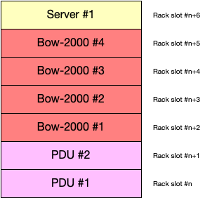
All Bow-2000s and the server should be adjacent to each other in the rack, with the server installed above the Bow-2000s. If you are using horizontal PDUs, then you need 7 adjacent rack slots (Fig. 2.1). If you are using vertical PDUs, then you need 5 adjacent rack slots.
Fig. 2.1 Schematic of locations of components in the rack for a Bow Pod16 with horizontal PDUs.
Table 2.1 shows the additional equipment needed for the expansion. This is based on the assumption that you already have the equipment listed in Table 2.2.
Table 2.1 Additional equipment to expand a single Bow-2000 system to Bow Pod16 DA
Description
Additional Quantity
Notes
Blanking panels (APC AR8136BLK)
for every unoccupied rack slot at the front of the rack
Graphcore Bow-2000
3
You will need to buy 3 additional Bow-2000s Founder’s Edition kits.
Bow-2000 slider kits
3
Included with Bow-2000 Founder’s Edition kits
0.3m blue Ethernet
3
Included with Bow-2000 Founder’s Edition kits
0.15m red Ethernet
6
Included with Bow-2000 Founder’s Edition kits
1.5m QSFP28
3
Included with Bow-2000 Founder’s Edition kits
0.3m OSFP
12
Included with Bow-2000 Founder’s Edition kits
Table 2.2 Existing equipment (from the single Bow-2000 system)
Turn the power off on all systems in the rack before starting with the expansion.
Note
If the single Bow-2000 system was installed without space for expansion, then you will have to move the Bow-2000 and the server in order to make space for the new Bow-2000s.
If you need to remove the Dell R6525 server from the rack:
Press the slide-release lock buttons on both rails and slide the server completely out of the rack.
There are lock levers on the sides of the inner rails. Rotate each lever upwards to release the server from the rails.
Firmly holding the sides of the server, and pull it forward until the tabs are at the front of slots. Lift the server up and remove from the rails.
Place the server on a level surface.
To remove the rails from the rack, pull the latch release button on the midpoint of the front and back of each rail. This releases the rail from the rack. Remove the rail.
For removing other servers from the rack, please refer to their manufacturer instructions.
Prepare an appropriate server lift and adjust the height such that it is suitable for the IPU-Machine sliders. If a lift is not available, then this is a two-person operation.
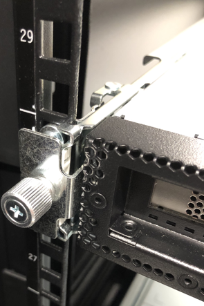
Unscrew the captive thumb screws at the front of both the inner rack rails (Fig. 2.4).
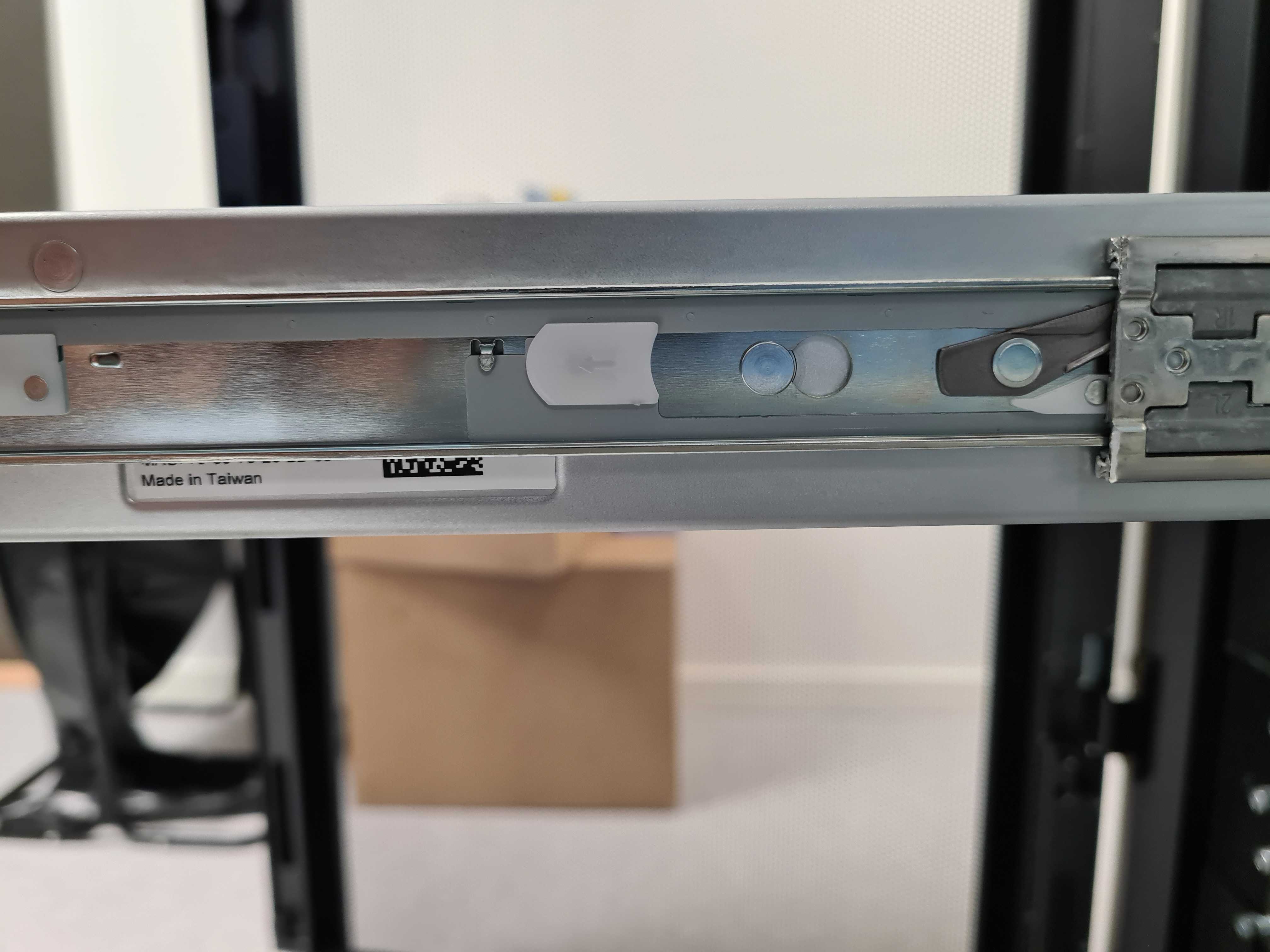
Completely slide out the IPU-Machine on the rails.
Pull on the white tabs (Fig. 2.5) on both sides of the IPU-Machine to release it. Pull the IPU-Machine forwards until it starts sliding out of the outer rails.
If you need to move the IPU-Machine, then you need to remove the IPU-Machine rails from the rack.
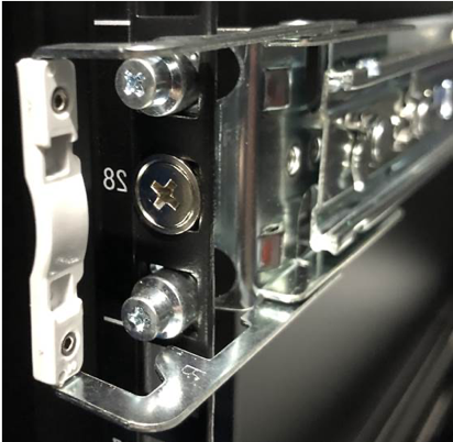
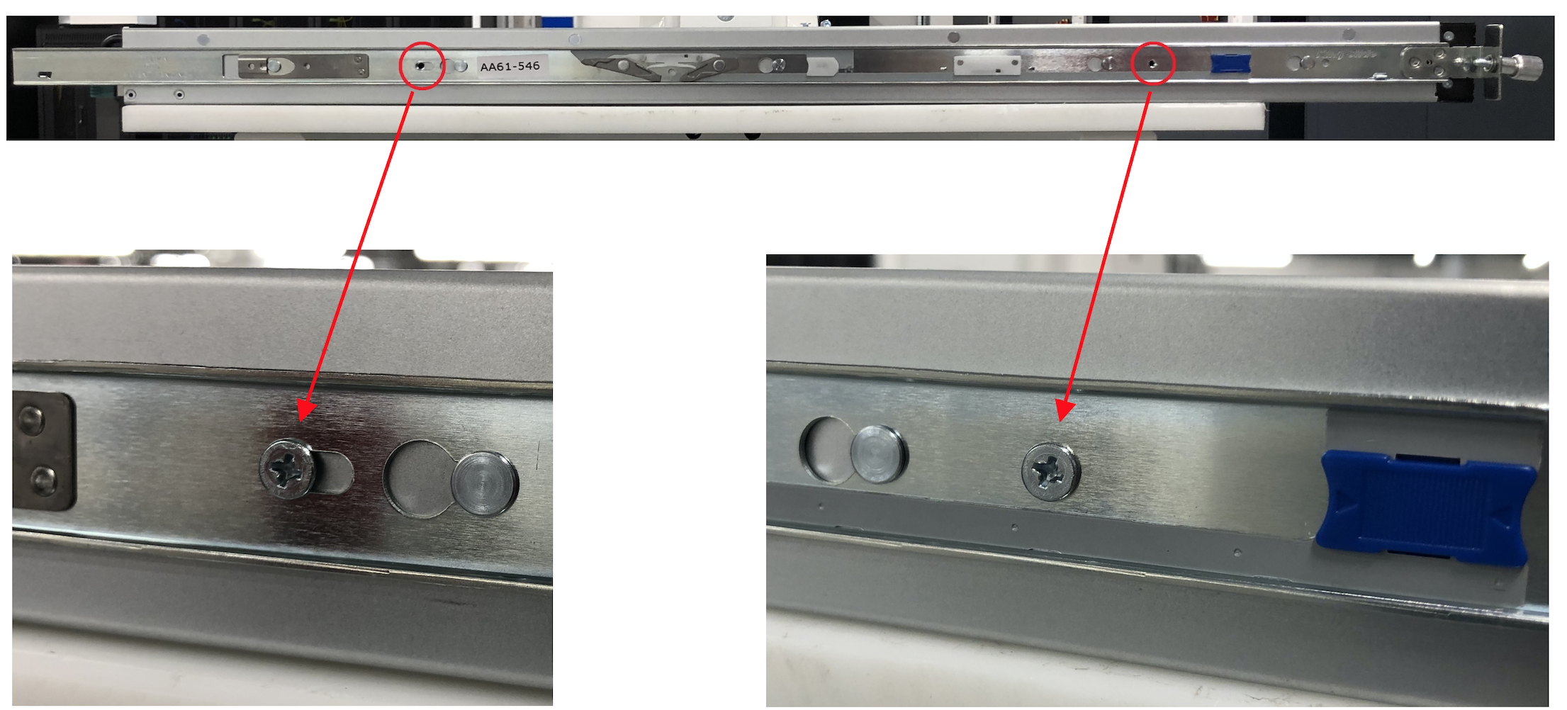
For the rear end of the outer rail, remove the screw with the washer from the midpoint of the vertical rack rail (Fig. 2.6).
Fig. 2.6 Remove the screw from the centre of the endpiece of the rail.
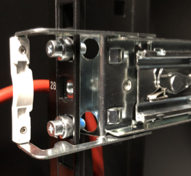
Release the rear end of the outer rail by slightly opening the large metal latch (pull on the white tab in Fig. 2.7), then lifting the upper and lower locating pins from the square holes on the vertical rack rail. The rear end of the outer rail will now be free of the rack.
Fig. 2.7 Open large metal latch to release rear end of outer rail
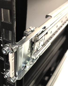
Release the front end of the outer rail by opening the latching mechanism (Fig. 2.8). Lift the rail and pull/push it towards/away from you. The rail will now be free of the rack.
Fig. 2.8 Open large metal latch to release front end of outer rail
The method for installing the PDUs will depend on the choice of PDU type and location. If the PDUs are to be installed horizontally within the rack, the recommendation is that these are positioned beneath the lowest Bow-2000. Allowing some space between the lowest Bow-2000 and the PDUs may make power cabling easier.
The Bow-2000 rails should be installed in the rack so that there is enough space for all Bow-2000s, the PDUs and the host server.
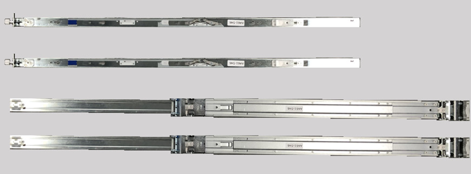
The IPU-Machine rail kit comprises two mated inner and outer rack rails and an accessory bag containing screws. The inner rail affixes to the body of the IPU-Machine and the outer rail affixes to the vertical rack rails in the server cabinet.
Repeat these instructions for each IPU-Machine to be installed.
Separate the mated inner and outer rails.
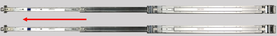
Fully extend the rails by pulling on the end which has the captive thumb screw attached (Fig. 2.9).
To affix the inner rail to the body of the IPU-Machine, mate the inner rails (the thinner of the two separated rails which has a captive thumb screw at one end) to the body of the IPU-Machine. Note that the inner rails are identical. As such, the procedure for inner rail fixing is the same for the left and right hand inner rails.
The inner rail should be oriented such that the captive thumb screw end is at the end of the IPU-Machine containing the network ports.
Place the inner rail to the side of the IPU-Machine and ensure that all fixing pins are sitting within the enlarged opening of the retention channel (Fig. 2.12).
Push the inner rail towards the end of the IPU-Machine containing the network ports, you should hear a click as the latching mechanism locks behind the head of a fixing pin (Fig. 2.13).
The inner rails are now securely affixed to the IPU-Machine body.
Install the outer rack rails in the rack.
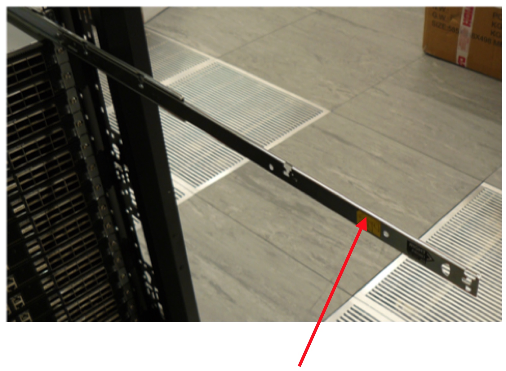
Locate the front and rear of the outer rail. The front of the outer rail is embossed with the word “FRONT” and the rear of the outer rail has a large metal latch (as shown in Fig. 2.16).
Fig. 2.16 Attachment point for the rear of the IPU-Machine outer rail
Pull on each end of the outer rail to adjust the rail length to suit your rack
Hold the front end of the outer rail (embossed with the word “FRONT”) behind the square holes in the vertical rack rail. Pull the outer rail towards the vertical rack rail and the latching mechanism will click and hold the outer rail in place (Fig. 2.17).
Fig. 2.17 IPU-Machine outer rail front latching mechanism
Hold the rear end of the outer rail and slightly open the large metal latch, then press the upper and lower locating pins into the square holes in the vertical rack rail. Release the large metal latch and the outer rail will now be secured to the vertical rack rail (Fig. 2.18).
Fig. 2.18 Rear of IPU-Machine outer rail secured to vertical rack rail
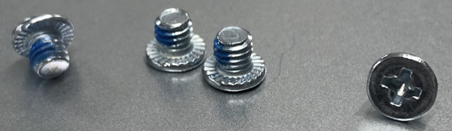
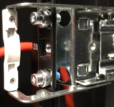
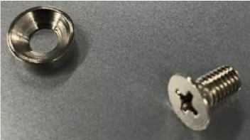
Find the screws and washers (Fig. 2.19) in the rack rail accessory bag. One screw and one washer should be screwed through the vertical rack rail and into the outer rack rail threaded hole. The washer should be used in such a way that the washer sits flush with the head of the screw –like a cup (Fig. 2.20).
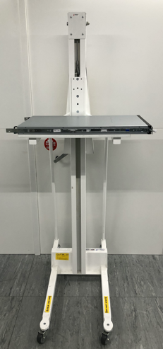
Place the IPU-Machine onto an appropriate server lift and adjust the height such that it is suitable for the sliders (Fig. 2.22). If a lift is not available, this is a two person operation.
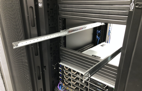
Slide the protruding inner rails (on the IPU-Machine) into the receiving channel of the extended outer rails (Fig. 2.23).
Fig. 2.23 Slide IPU-Machine inner rails into outer rails
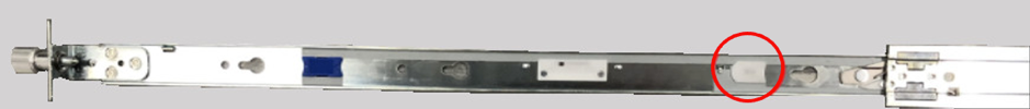
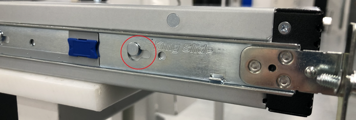
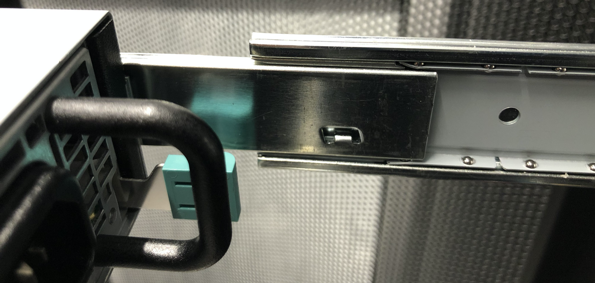
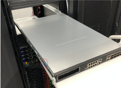
Whilst the server lift is supporting the full weight of the IPU-Machine (or with two people carrying the IPU-Machine if not using a server lift), slide the IPU-Machine into the extended outer rails until you feel both sides engage a stopping mechanism (Fig. 2.25).
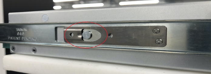
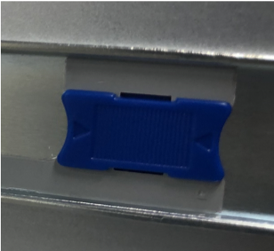
Then, simultaneously pull on the blue tabs for the release mechanism at each side of the IPU-Machine and then push the IPU-Machine unit fully into the rack (Fig. 2.24 and circled in Fig. 2.25).
The server should be installed above the four Bow-2000s.
This section describes the installation of a Dell R6525 server. A list of approved and qualified servers is available. To find out more, speak to Graphcore sales or your Graphcore channel partner.
Note
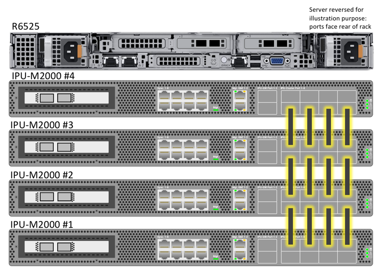
The R6525 is installed such that the rear of the server (containing the management and data ports) is on the opposite side of the rack to the ports on the front of the IPU-Machine(s). This is due to the airflow direction.
Install the tool-less sliding rail kit(s).
Pull out the rail and fit the server to the rail ensuring the T pins on the side of the server locate in the slots on the rail. Ensure that the power supplies on the server face the rear of the rack (Fig. 2.27).
Fig. 2.27 Sliding rail kit for server installation
Note
Use an appropriate server lift or have two people installing the server to ensure correct fitting
Push the server gently from the front to lock it into the slides then press the tab on the side of the slides and push the server fully home in the rack. Repeat the above process for each server if installing multiple servers.
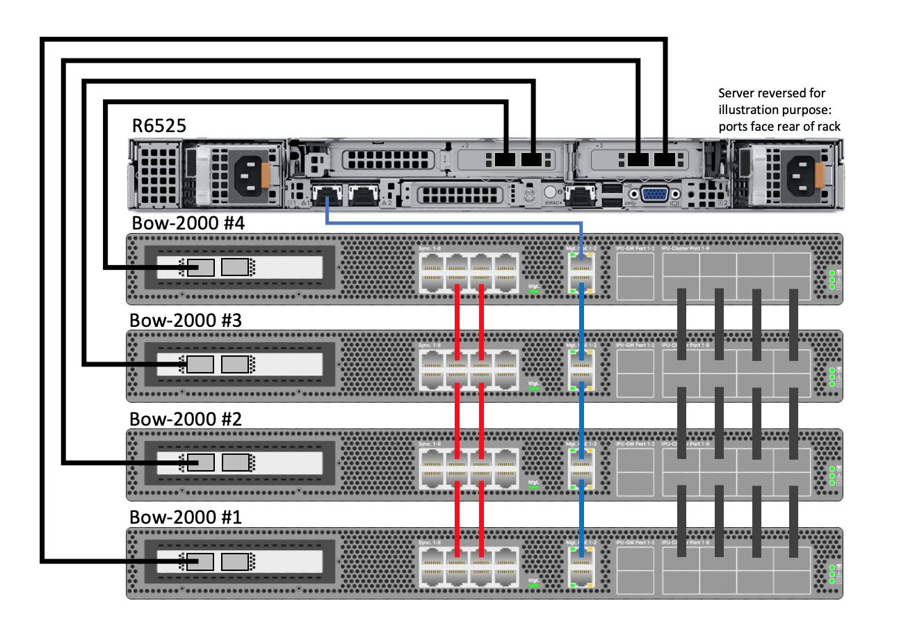
The cabling is very straightforward, as indicated by diagram of the completed system Fig. 2.28. The following sections take you through wiring up each group of cables in turn.
Fig. 2.28 Completed cabling for a Bow Pod16 DA system
2.5.1. Bow-2000 to Bow-2000 IPU-Link connectivity (OSFP)
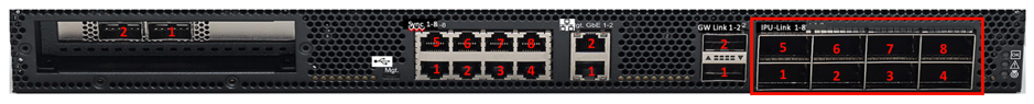
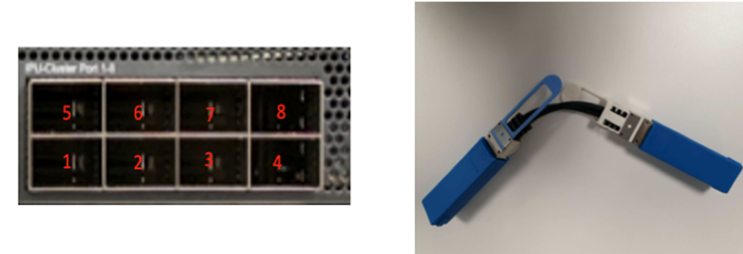
There are 8 OSFP IPU-Link ports on the right side of each Bow-2000.
Using 0.3M OSFP cables, link the top row of four IPU-link ports (5-8) to the bottom row of four IPU-link ports (1-4) in the Bow-2000 that is installed directly above (see Table 2.3 and Fig. 2.30). The top row (5-8) of the top-most Bow-2000 (#4) and the bottom row (1-4) of the bottom-most Bow-2000 (#1), are left unconnected.
Fig. 2.30 Bow-2000 to Bow-2000 IPU-Link cabling for a Bow Pod16 DA system
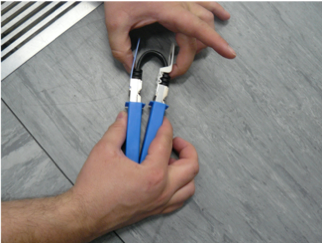
Before attempting to install the OSFP cables, it is beneficial to manipulate the cable to form a tight loop such that the white side of the connector tabs face away from each other. During manufacture and shipping, the cables can form quite a stiff shape, so manipulating the cables (Fig. 2.31) before installing them reduces stresses on the socket during install.
Fig. 2.31 Manipulate the OSFP cables before installing
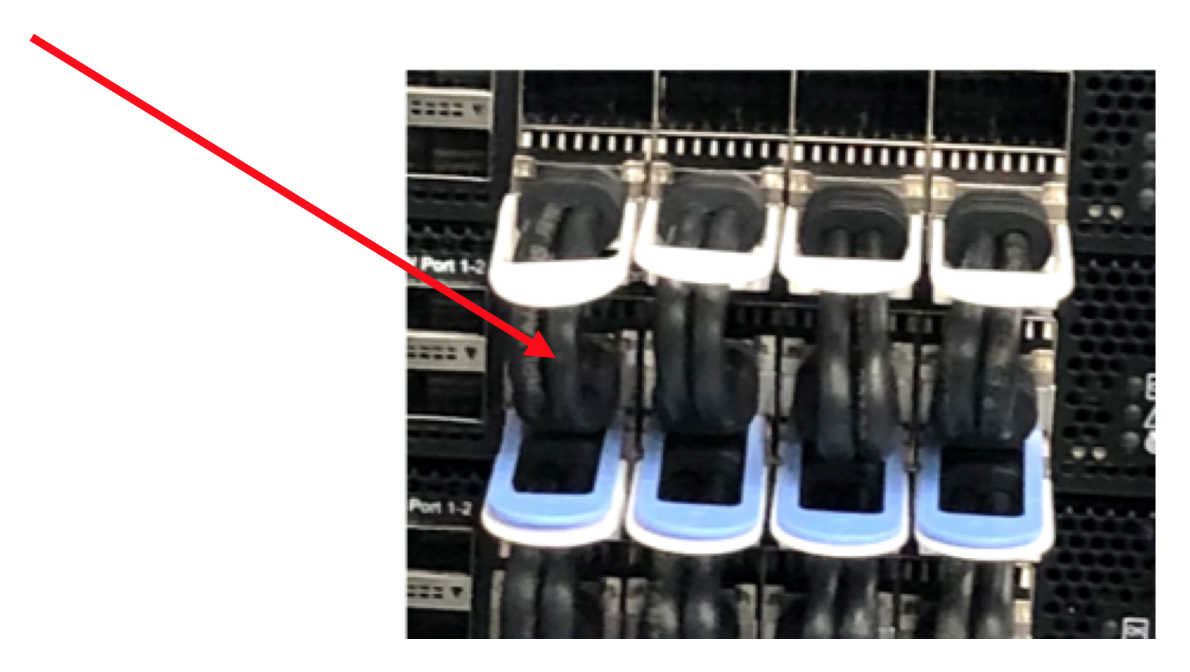
After installing a cable, pull gently on the black cable to ensure the plugs are firm in the sockets on the Bow-2000.
Fig. 2.32 Pull gently on the black cable to ensure that they are firmly connected
Note
The white tab is on the top of the cable when inserted into the Bow-2000.
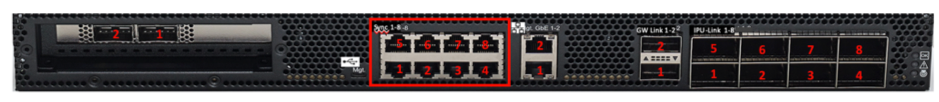
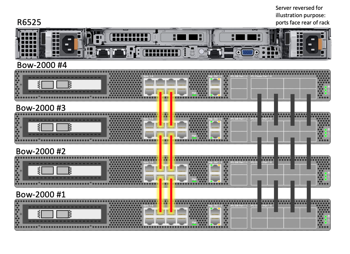
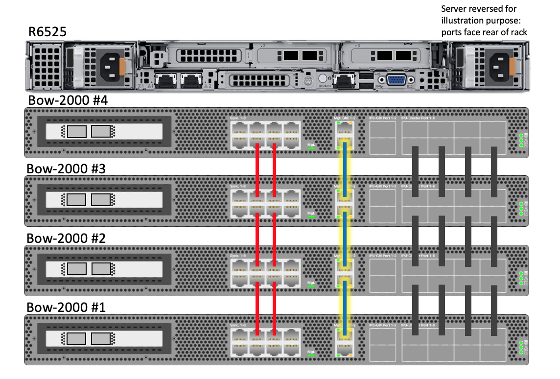
Using 0.15m red Ethernet Cat5e cables, link the top two central Sync-Link ports (6-7) of each Bow-2000 to the bottom two central Sync-Link ports (2-3) of the Bow-2000 that is installed directly above (as described in Table 2.4 and shown in Fig. 2.34). The top row (5-8) of the top-most Bow-2000 (#4) and the bottom row (1-4) of the bottom-most Bow-2000 (#1), are left unconnected.
Fig. 2.34 Bow-2000 Sync-Link cabling for a Bow Pod16 DA system
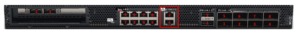
Using 0.3m blue Ethernet Cat5e cables, link the top management port (2) of each Bow-2000 to the bottom management port (1) of the Bow-2000 that is installed directly above (as described in Table 2.5 and shown in Fig. 2.36). The top management port (2) of the top-most Bow-2000 (#4) and the bottom management port (1) of the bottom-most Bow-2000 (#1), are left unconnected.
Fig. 2.36 Bow-2000 management cabling for a Bow Pod16 DA system
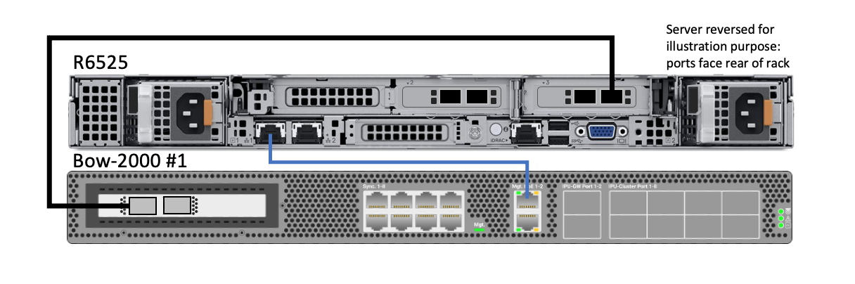
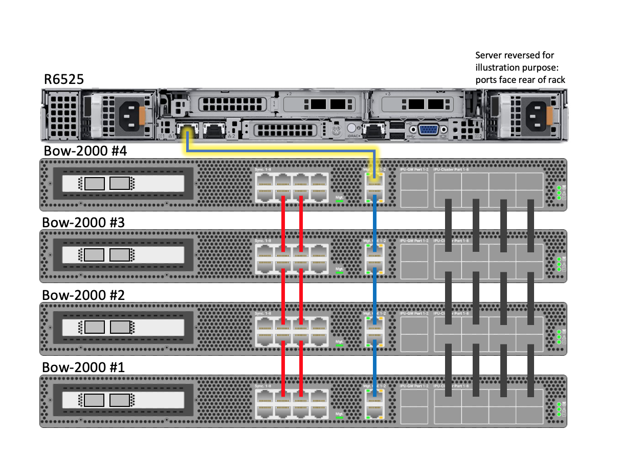
Using a 1.5m blue Ethernet Cat5e cable, link the top management port (port #2) of the top Bow-2000 to management port #1 of the R6525 server, as described in Table 2.6 and shown in Fig. 2.38.
Fig. 2.38 Bow Pod16 DA system (Bow-2000 to server management cabling)
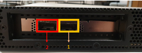
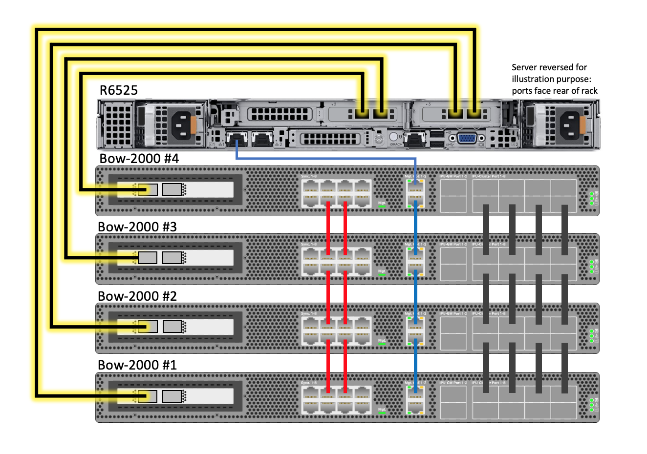
Only one of these (port #2) should be connected from each Bow-2000 to the server with 1.5m QSFP cables, as described in Table 2.7 and shown in Fig. 2.40.
Fig. 2.40 Bow Pod16 DA system (Bow-2000 data cabling)
Note
Bow-2000 #1 (the lowest in the stack) is always connected to Port 1 in server slot 3.
The method for cabling the PDUs will depend on the choice of PDU and location. Each Bow-2000 has two power inputs and these should be supplied from separate power distribution units for redundancy.
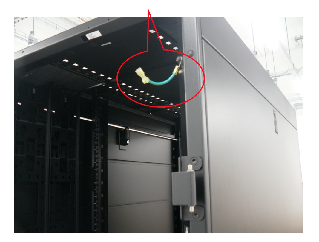
Re-install the top and bottom side panels on each side of the rack. Ensure the earth cables are reconnected to the cable on the rack. Re-install the front and rear doors.
2.8. Upgrade software on host server and Bow-2000
To complete the expansion from a single Bow-2000 system to a Bow Pod16, you need to upgrade the software on the host server and on the Bow-2000s. This process is described in the System platform software configuration section of the Bow Pod DA Build and Test Guide.
Note
Because you have a configured system, when you run the Bow Pod DA install script, it will start by asking you to accept the current configuration. You must answer “n” so that you can increase the number of Bow-2000s in your system from 1 to 4.