Note: Searching from the top-level index page will search all documents. Searching from a specific document will search only that document.
Find an exact phrase: Wrap your search phrase in "" (double quotes) to only get results where the phrase is exactly matched. For example "PyTorch for the IPU" or "replicated tensor sharding"
Prefix query: Add an * (asterisk) at the end of any word to indicate a prefix query. This will return results containing all words with the specific prefix. For example tensor*
Fuzzy search: Use ~N (tilde followed by a number) at the end of any word for a fuzzy search. This will return results that are similar to the search word. N specifies the “edit distance” (fuzziness) of the match. For example Polibs~1
Words close to each other:~N (tilde followed by a number) after a phrase (in quotes) returns results where the words are close to each other. N is the maximum number of positions allowed between matching words. For example "ipu version"~2
Logical operators. You can use the following logical operators in a search:
+ signifies AND operation
| signifies OR operation
- negates a single word or phrase (returns results without that word or phrase)
The Bow-2000 mounting system requires a rail-to-rail distance of 720mm. This document describes the adjustments required for an AR3300SP rack. If using a different rack this rail distance must be observed.
Follow the instructions to remove the outer packaging of the APC AR3300SP rack, ensuring that you safely store these materials for later repackaging. Do not remove the rack from the shock pallet.
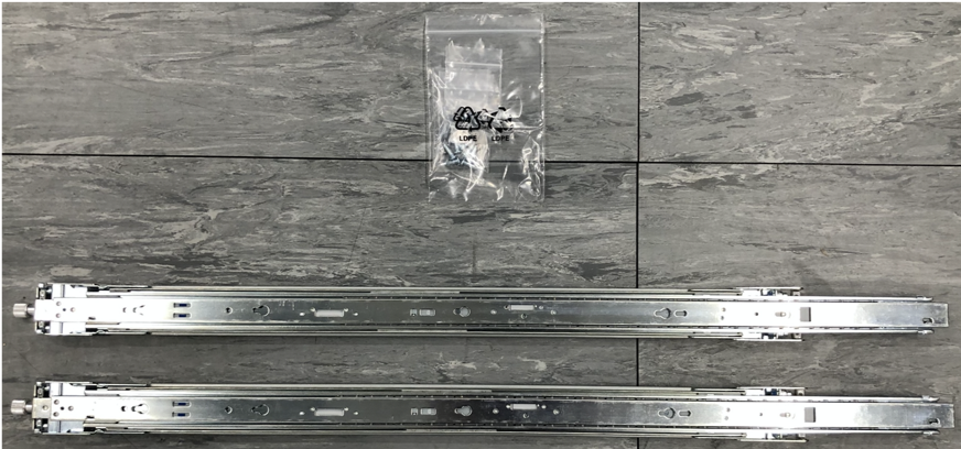
Remove the white bag (Fig. 4.1) from the rack. This contains screws and cage nuts to be used in the assembly of the components into the rack.
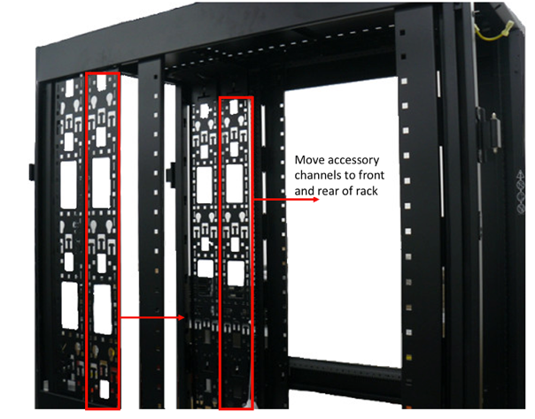
Remove the top and bottom side panels. The vertical accessory channels should be positioned at the very front and very rear of the rack. If necessary, move these from their shipping positions (Fig. 4.3).
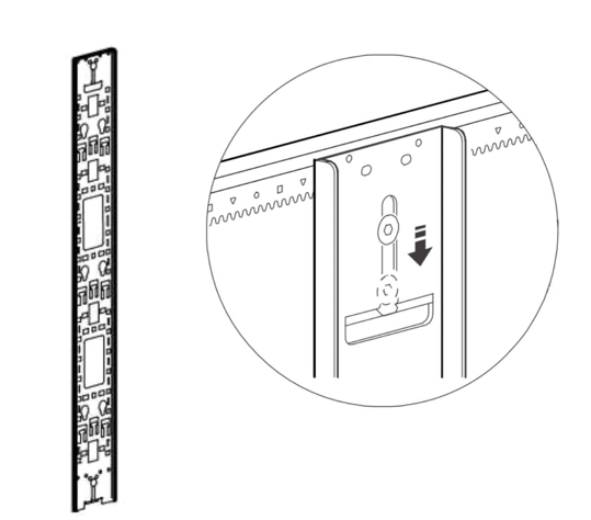
Set the rear accessory channel to the furthest position in the rack.
Tighten up the screws ensuring the teeth engage into the slots in the rail, as shown in Fig. 4.5.
Fig. 4.5 Rear accessory channel (ensure teeth engage in slots)
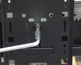
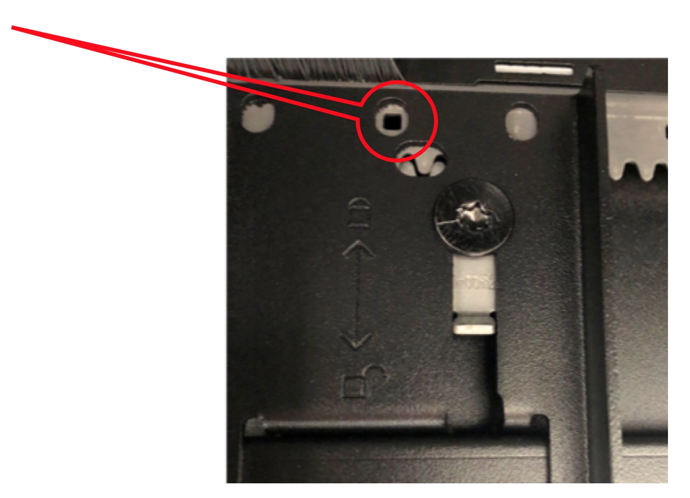
Using a Torx TX30 screwdriver, make both rear vertical rack rails loose and freely movable.
Position the rear vertical rack rails such that there is 20mm of distance between the rear face of the vertical rack rail and the racks rear frame. This should result in a square symbol being visible through the alignment window at the top and bottom of the rail, as shown in Fig. 4.6.
Secure the rail into position by moving the TX30 screws back upwards such that the teeth engage with both the supporting rails. This must be done at the top and bottom of the bracket.
Using a Torx TX30 screwdriver, make both front vertical rack rails loose and freely movable.
Install the accessory channels in the front of the rack (one on the left hand side, one on the right hand side) at the frontmost position possible, moving the TX30 screws back upwards such that the teeth engage with both the supporting rails. This must be done at the top and bottom of the bracket.
Note
To ensure the clips on the accessory channels align with the channel in the rack, lift the accessory channels through the cut-out in the top of the rack and then drop them down onto the channels.
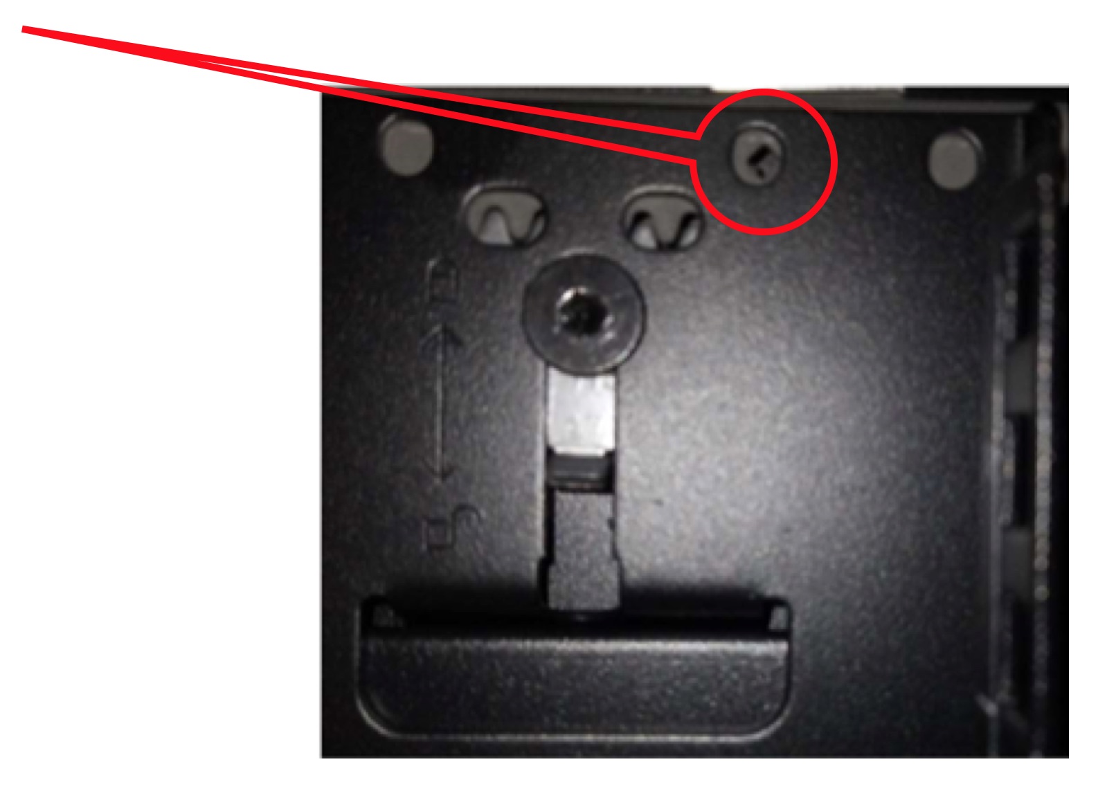
Move the vertical rack rails tight against the vertical cable organisers such that only a single diamond symbol is visible through the alignment window at the top and bottom of the rail, see Fig. 4.7.
Secure the rail into position by moving the TX30 screws back upwards such that the teeth engage with both the supporting rails. This must be done at the top and bottom of the bracket.
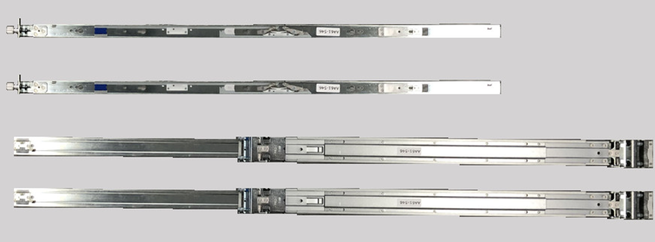
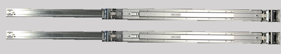
The Bow-2000 rail kit comprises two mated inner and outer rack rails and an accessory bag containing screws. The inner rail affixes to the body of the Bow-2000 and the outer rail affixes to the vertical rack rails in the server cabinet.
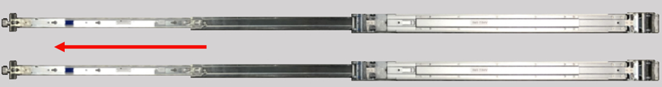
Firstly, separate the mated inner and outer rails:
Fully extend the rails by pulling on the end which has the captive thumb screw attached (Fig. 4.9):
Mate the inner rails (the thinner of the two separated rails which has a captive thumb screw at one end) to the body of the Bow-2000. Note that the inner rails are mirrored and are not handed. As such, the procedure for inner rail fixing is the same for the left and right hand inner rails.
The inner rail should be oriented such that the captive thumb screw end is at the end of the Bow-2000 containing the network ports.
To affix the inner rail to the body of the Bow-2000:
Offer up the inner rail to the side of the Bow-2000 and ensure that all fixing pins are sitting within the enlarged opening of the retention channel (Fig. 4.12):
Push the inner rail towards the end of the Bow-2000 containing the network ports, you should hear a click as the latching mechanism locks behind the head of a fixing pin (Fig. 4.13):
Screw the PDU support brackets to the inside of the cabinet.
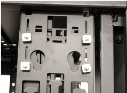
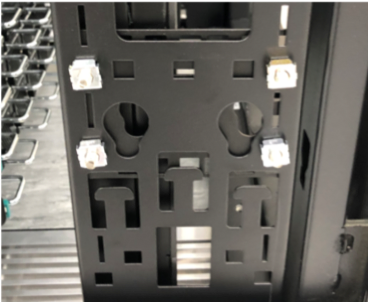
The PDU brackets should be installed at the rear of the rack: one bracket on top with 9cm distance from the top of rack and one bracket on the bottom with 12cm distance from the bottom of rack. Fig. 4.19 illustrates this. Follow the PDU bracket installation instructions.
The following sections describe the installation of the Bow-2000(s) and server into the rack.
Clearly in the case of a single Bow-2000 DA system only one Bow-2000 is installed. If subsequently you plan to expand to a Bow Pod16 DA system, you may wish to leave enough free rack space (3 rows) between the Bow-2000 and the server.
In the case of a Bow Pod16 DA system, four Bow-2000s are installed. All Bow-2000s and the server should be adjacent to each other in the rack.
The installation of PDUs is not covered in this guide since that will depend upon the PDUs selected.
Earlier in the guide we affixed the inner rack rails to the Bow-2000 body. The next step in installing the Bow-2000 IPU-Machines is to install the outer rack rails into the rack.
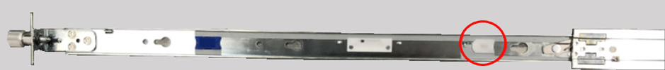
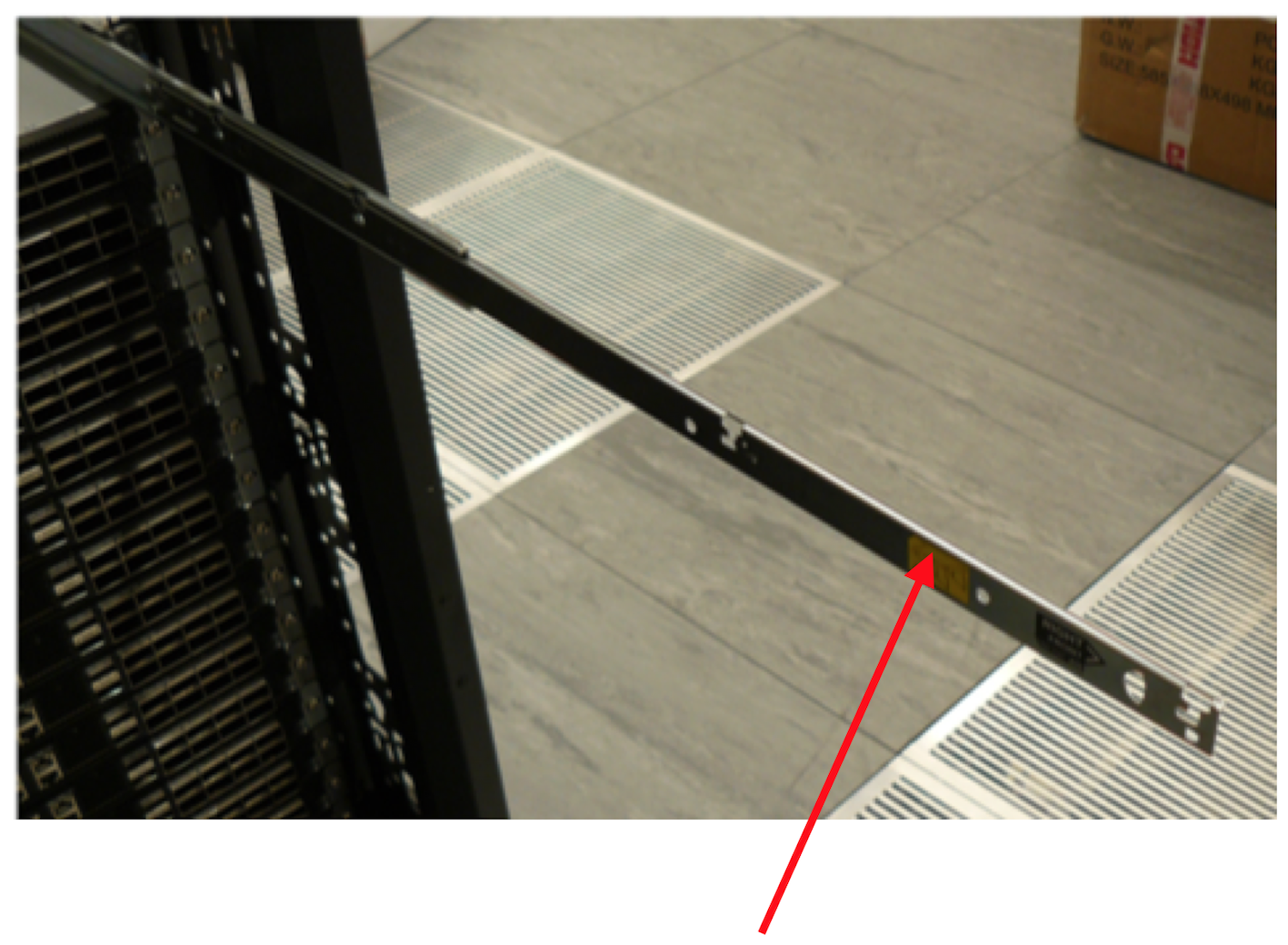
It is possible to identify the front and rear of the outer rail by finding the large metal latching mechanism. This is to be located at the rear of the rack. The outer rail is also embossed with the text “FRONT” at the front end of the rail.
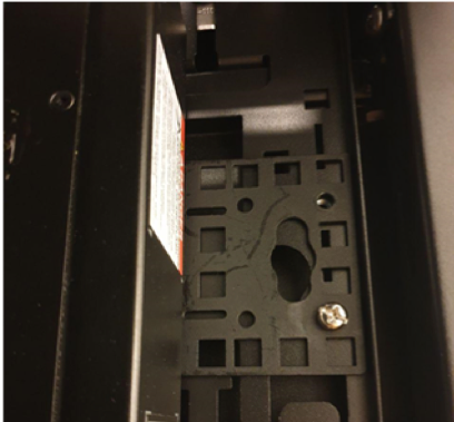
The outer rail large metal latch end is to be installed at the rear of the rack, as shown in Fig. 4.20.
Fig. 4.20 Attachment point for Bow-2000 outer rail
For each rack U in U1 through U16 (inclusive), perform the steps below with both the left hand and right hand outer rack rails:
Pull on each end of the outer rail to adjust the rail length to suite your rack
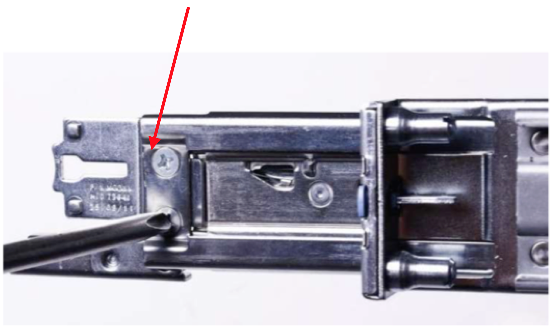
Locate the front end of the outer rail and hold it behind the square holes in the vertical rack rail for your installation U. Pull the outer rail towards the vertical rack rail and the latching mechanism will click and hold the outer rail in place (Fig. 4.21):
Locate the rear end of the outer rail and slightly open the large metal latch, then press the upper and lower locating pins into the square holes in the vertical rack rail. Release the large metal latch and the outer rail will now be secured to the vertical rack rail (Fig. 4.22):
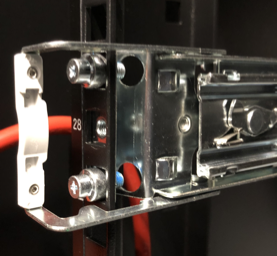
Fig. 4.22 Bow-2000 outer rail secured to vertical rack rail
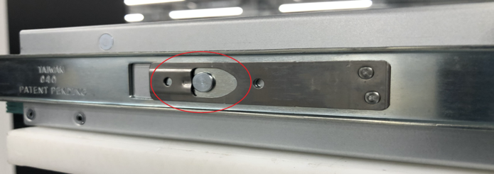
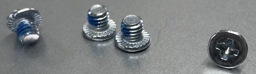
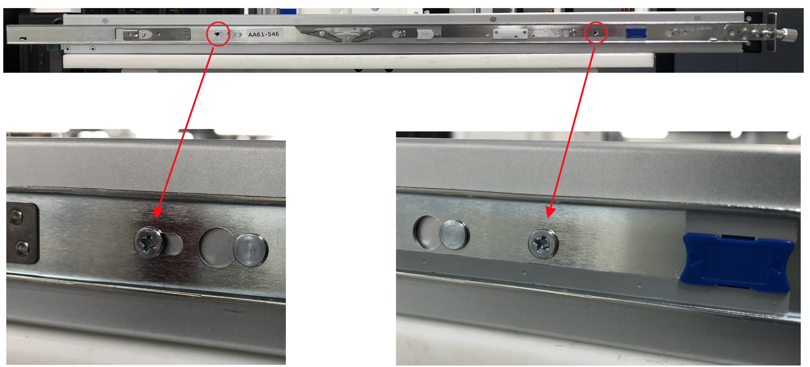
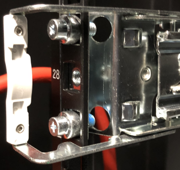
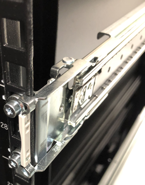
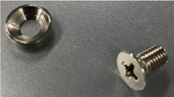
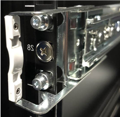
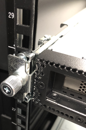
Included in the rack rail accessory bag are two screws and two washers. One screw with one washer should be screwed through the vertical rack rail and into the outer rack rail threaded hole. The washer should be used in such a way that the washer sits flush with the head of the screw –like a cup. The screws and how they fit are shown in Fig. 4.23 and Fig. 4.24.
This should be repeated for both outer rack rails.
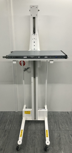
Place the Bow-2000 onto an appropriate server lift and adjust the height such that it is suitable for the sliders (Fig. 4.26). If a lift is not available, this is a two person operation.
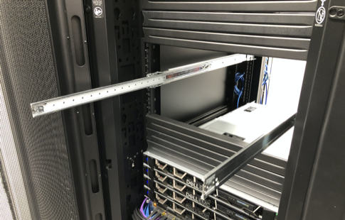
Slide the protruding inner rails into the receiving channel of the extended outer rails (Fig. 4.27):
Fig. 4.27 Slide Bow-2000 inner rails into outer rails
Whilst the server lift is supporting the full weight of the Bow-2000, slide the Bow-2000 into the extended outer rails until you feel both sides engage a stopping mechanism (Fig. 4.28).
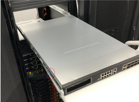
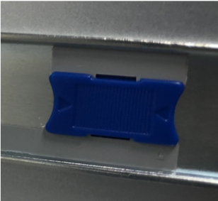
Simultaneously pull on the blue tabs for the release mechanism at each side of the Bow-2000 and then push the Bow-2000 unit fully into the rack (Fig. 4.29):
This section describes the installation of a Dell RG525 server. Other approved and qualified servers are available. To find out more speak to Graphcore sales or your Graphcore channel partner for options.
The server should be installed above the Bow-2000(s).
Note
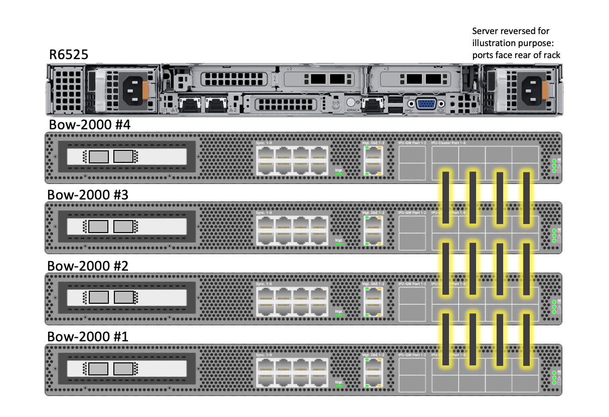
The R6525 is installed such that the rear of the server (containing the management and data ports) is the opposite side of the rack to the ports on the front of the Bow-2000(s). This is due to airflow direction.
Remove and discard the cable management arm brackets from the rear of each tool-less sliding rail.
Install the tool-less sliding rail kit(s) in the required location.
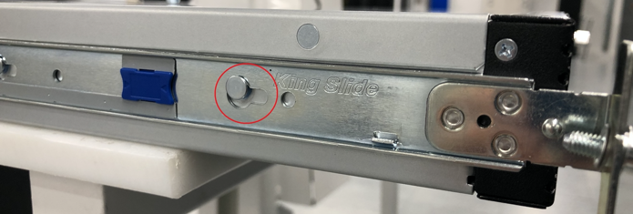
Pull out the rail and fit the server to the rail ensuring the T pins on the side of the server locate in the slots on the rail. Ensure that the power supplies on the server face the rear of the rack.
Note
Use an appropriate server lift or have two people installing the servers to ensure correct fitting
Push the server gently from the front to lock it into the slides then press the tab on the side of the slides and push the server fully home in the rack. Repeat the above process for each server if installing multiple servers.
Remove the Velcro tape from the light pipes on the rear of the servers.
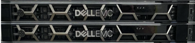
Remove the small plastic tab on the left front side of the server bezel and clip the bezel in place on the front of the server ensuring the connection pins on the right-hand side of the bezel line up with the connector on the server, as shown below:
The method for installing the PDUs will depend on the choice of PDU type and location. If the PDUs are to be installed horizontally within the rack, the recommendation is that these are positioned beneath the lowest Bow-2000. Allowing some space between the lowest Bow-2000 and the PDUs may make power cabling easier.
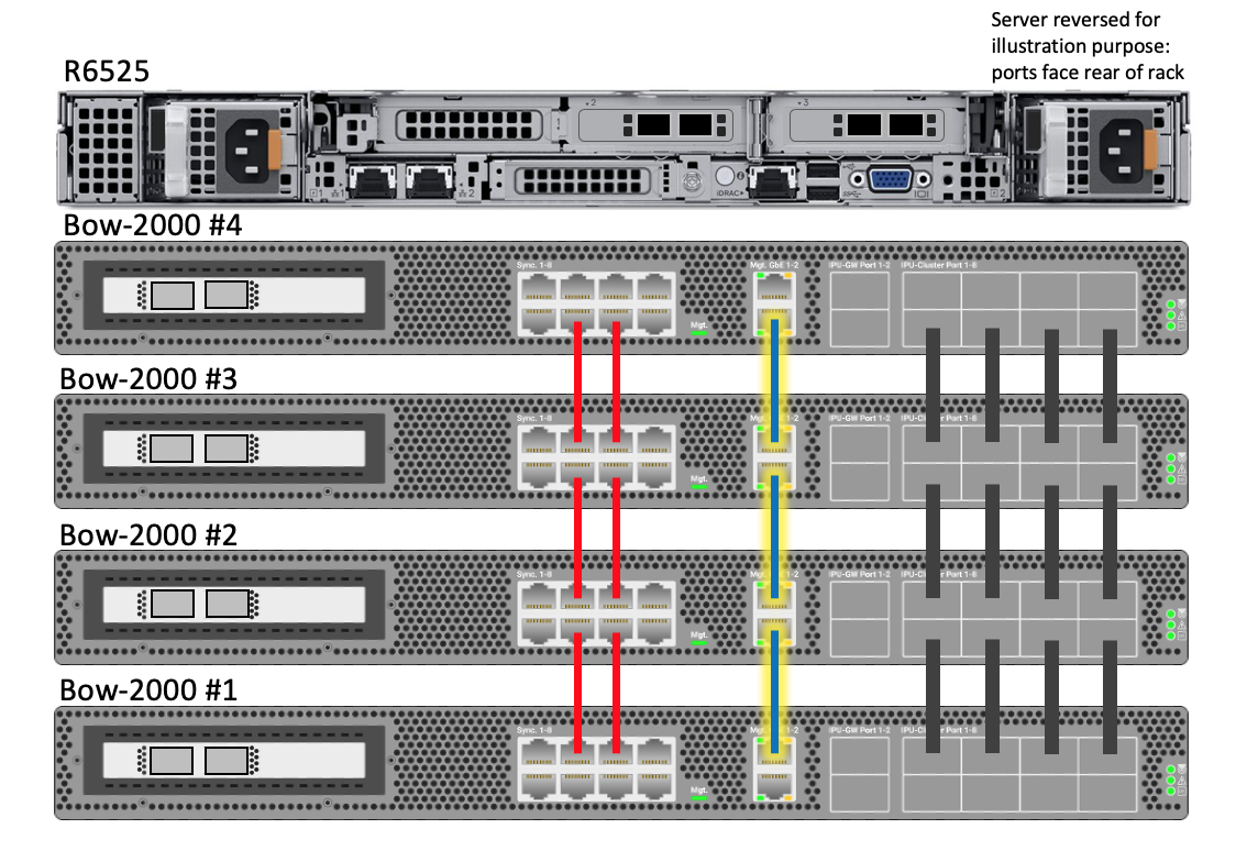
The following sections detail the wiring of the Bow Pod DA system within the rack. The cabling is very straightforward, as indicated by diagrams of the completed systems in Fig. 4.31 and Fig. 4.32. The following sections take you through wiring up each group of cables in turn.
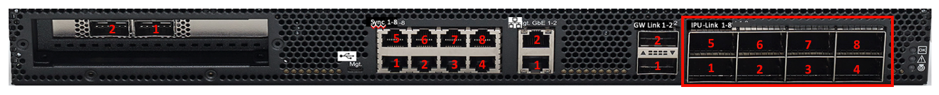
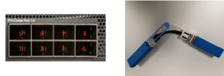
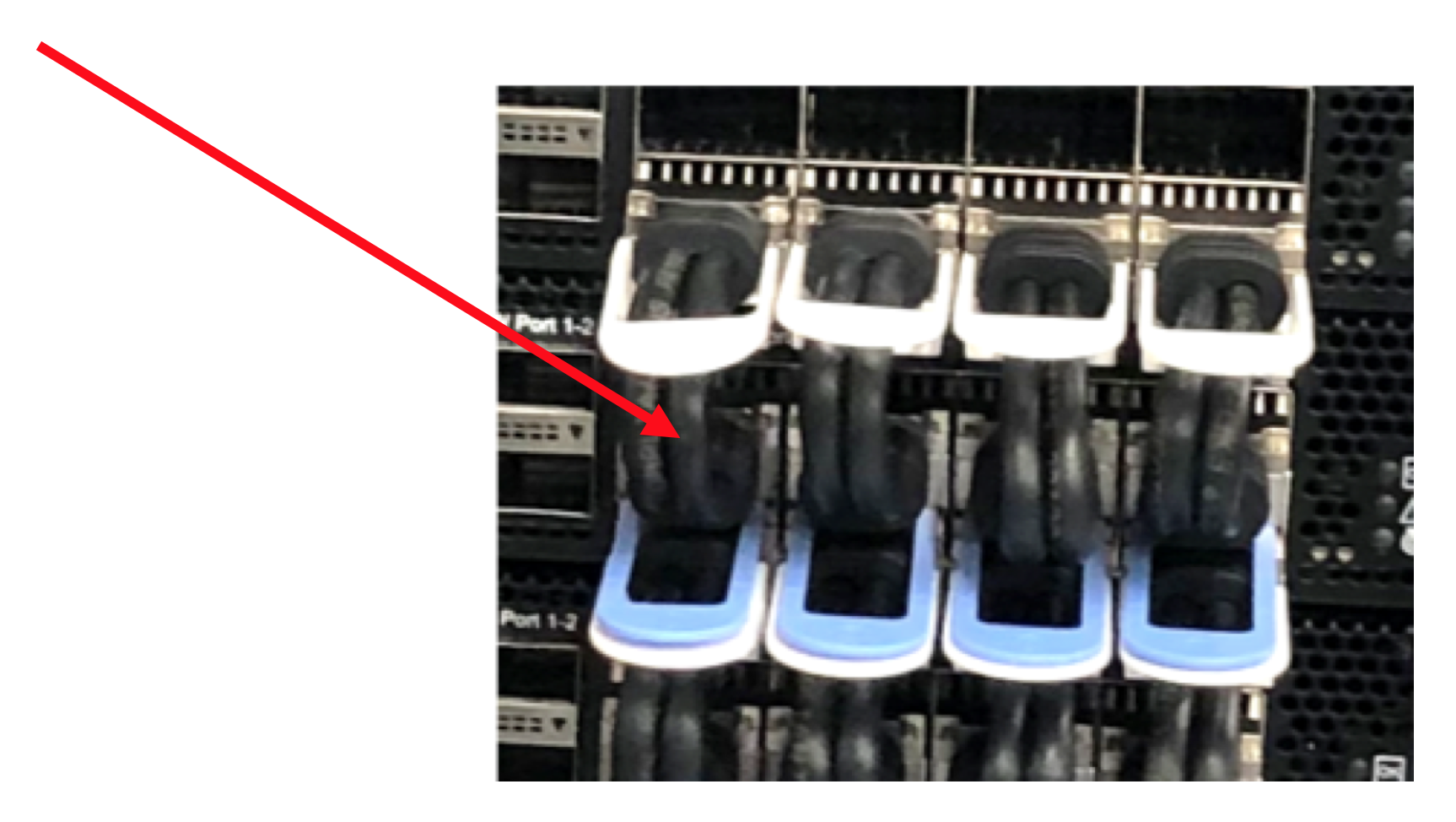
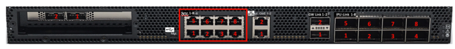
Using 0.3M OSFP cables, link the top row of four IPU-link ports (5-8) to the bottom row of four IPU-link ports (1-4) in the Bow-2000 that is installed directly above (see Table 4.1 and Fig. 4.34). The top row (5-8) of the top-most Bow-2000 (#4) and the bottom row (1-4) of the bottom-most Bow-2000 (#1), are left unconnected.
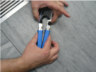
Before attempting to install the OSFP cables, it is beneficial to manipulate the cable to form a tight loop such that the white side of the connector tabs face away from each other. During manufacture and shipping, the cables can form quite a stiff shape, so manipulating the cables before installing them reduces stresses on the socket during install.
After installing a cable, pull gently on the black cable to ensure the plugs are firm in the sockets on the Bow-2000.
Note
The white tab is on the top of the cable when inserted into the Bow-2000.
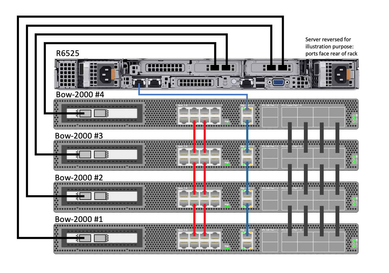
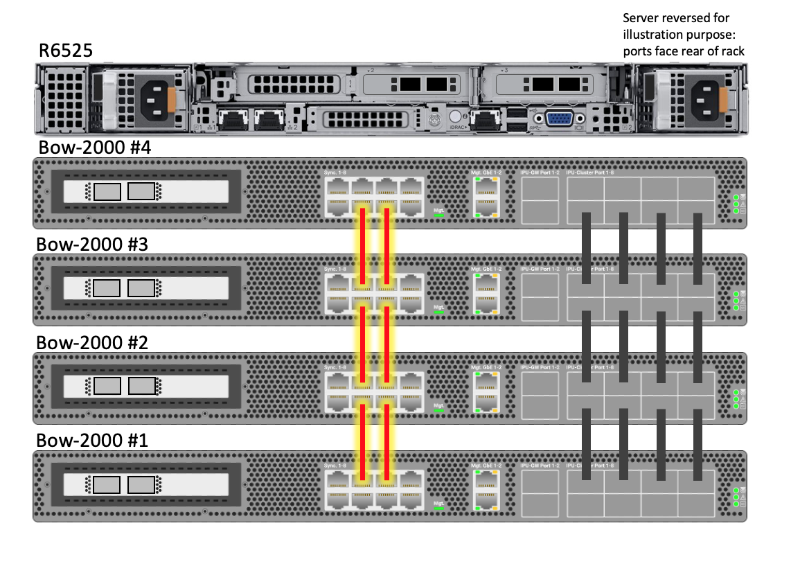
Using 0.15m red Ethernet Cat5e cables, link the top two central Sync-Link ports (6-7) of each Bow-2000 to the bottom two central Sync-Link ports (2-3) of the Bow-2000 that is installed directly above (see Table 4.2 and Fig. 4.36). The top row (5-8) of the top-most Bow-2000 (#4) and the bottom row (1-4) of the bottom-most Bow-2000 (#1), are left unconnected.
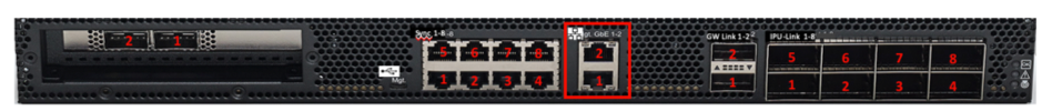
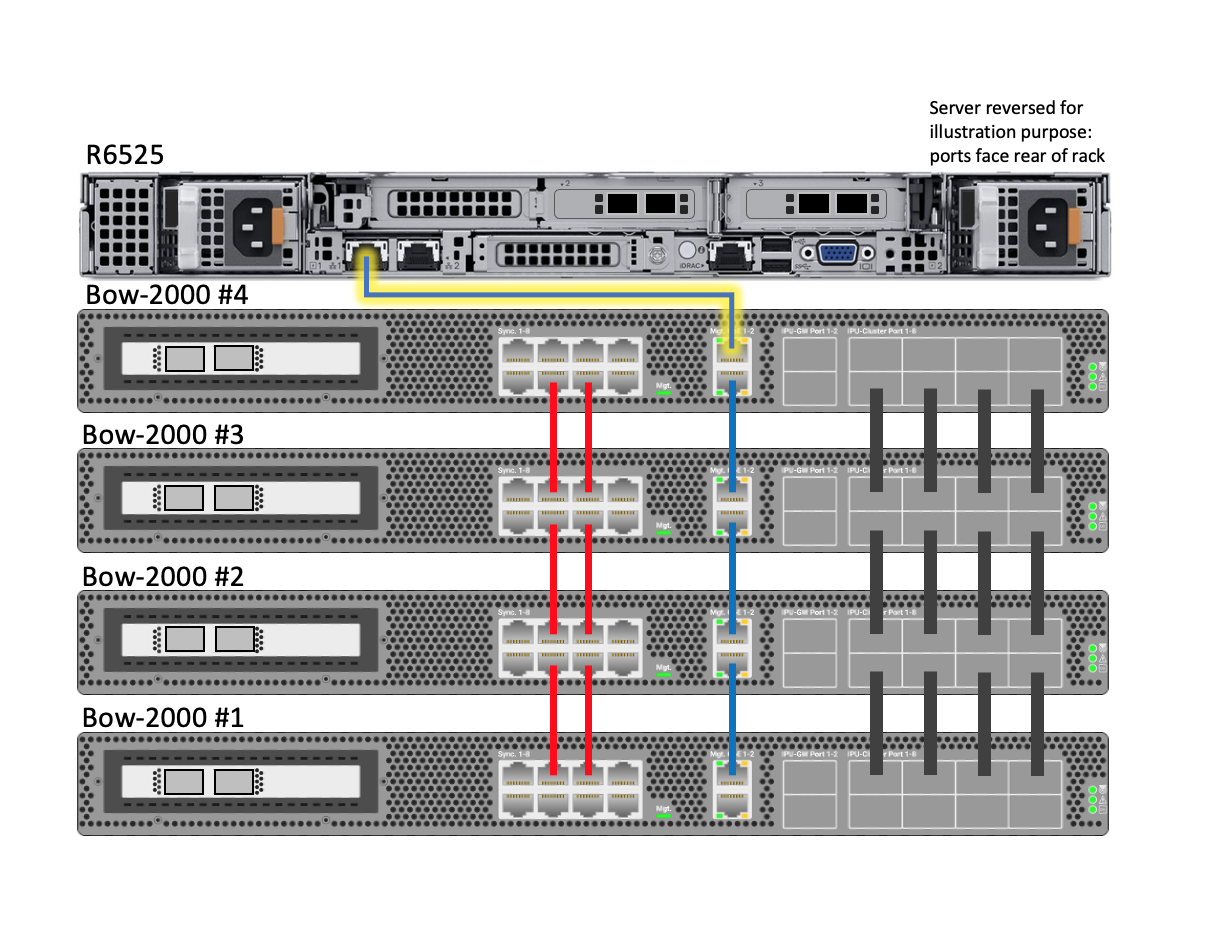
Using 0.3m blue Ethernet Cat5e cables, link the top management port (2) of each Bow-2000 to the bottom management port (1) of the Bow-2000 that is installed directly above (see Table 4.3 and Fig. 4.38). The top management port (2) of the top-most Bow-2000 (#4) and the bottom management port (1) of the bottom-most Bow-2000 (#1), are left unconnected.
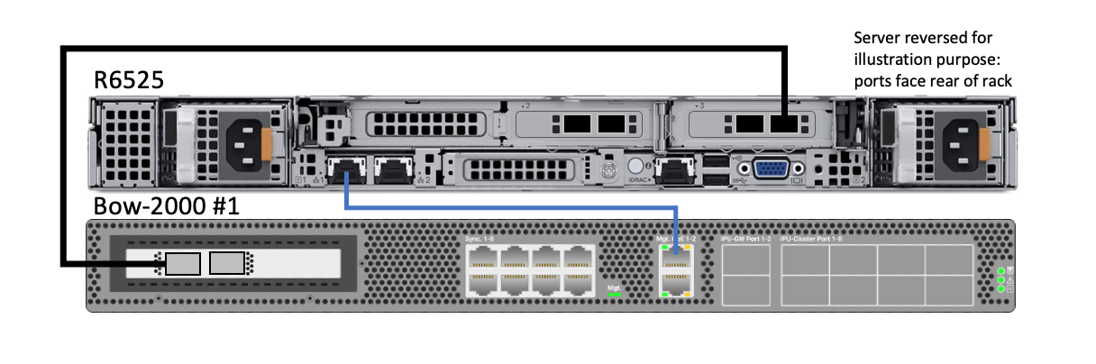
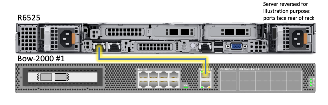
Using a 1.5m blue Ethernet Cat5e cable, link the top management port (port #2) of the top Bow-2000 to management port #1 of the R6525 server, as given in Table 4.4.
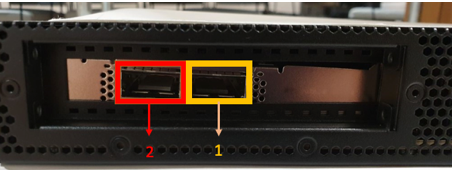
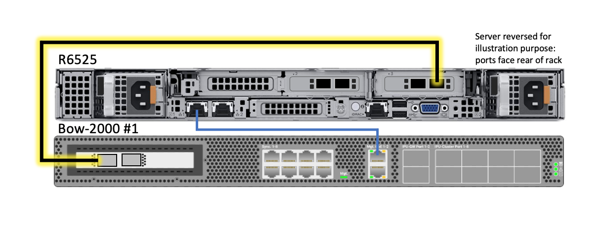
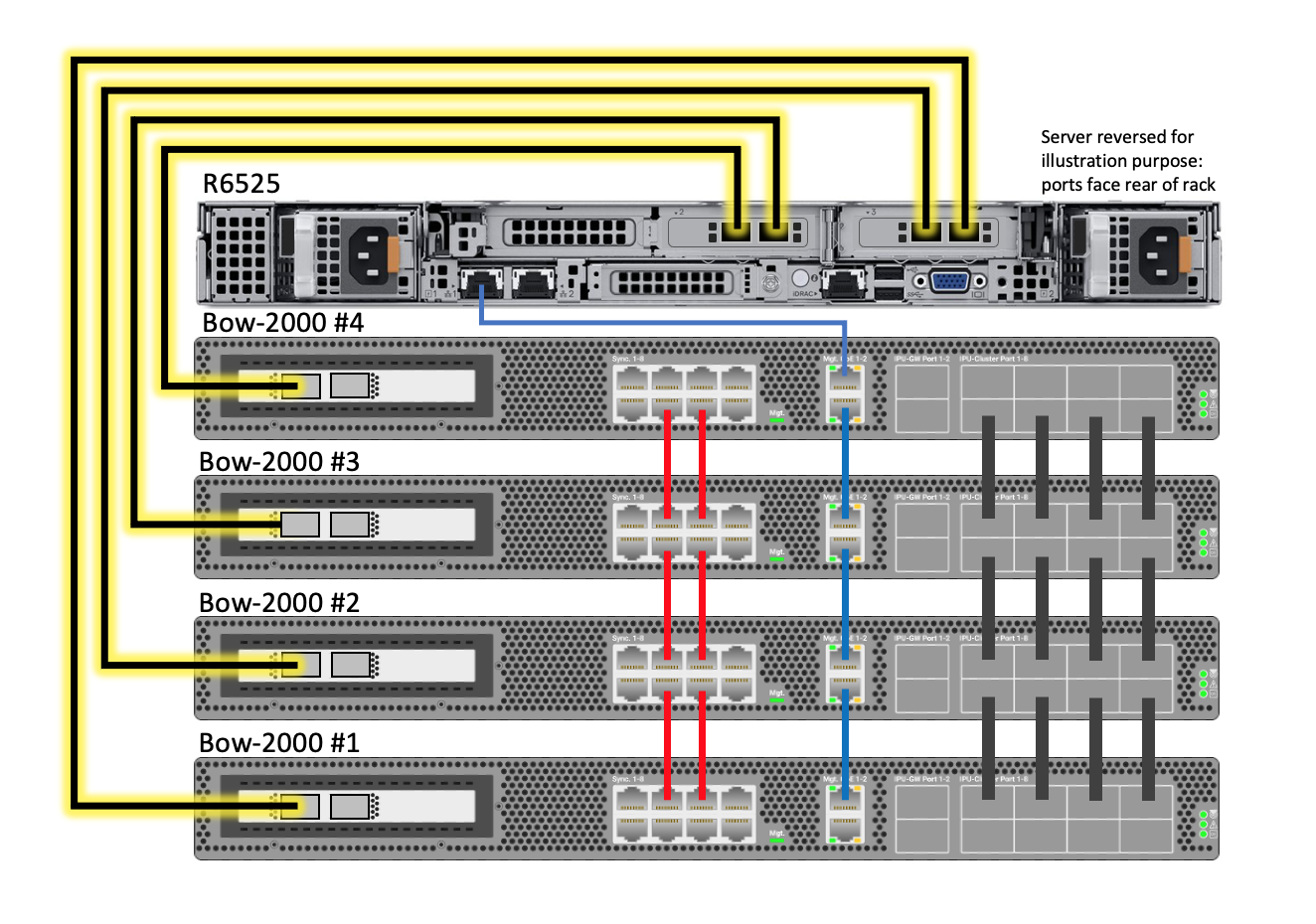
Only one of these (port #2) should be connected from each Bow-2000 to the server with 1.5m QSFP cables, as shown in Table 4.5. In a single Bow-2000 DA system, only Bow-2000 #1 is present.
The method for cabling the PDUs will depend on the choice of PDU type and location. Each Bow-2000 has two power inputs and these should be supplied from separate power distribution units for redundancy.
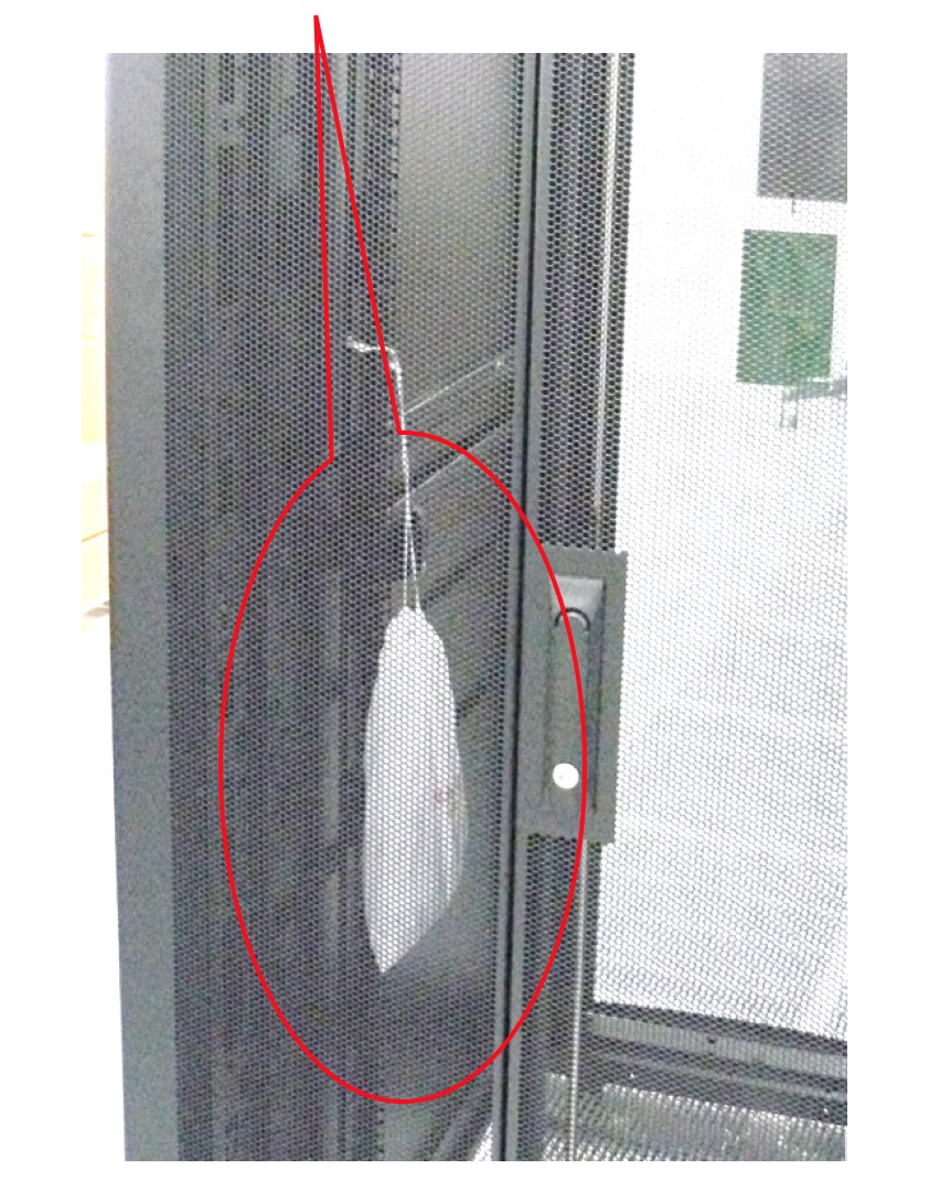
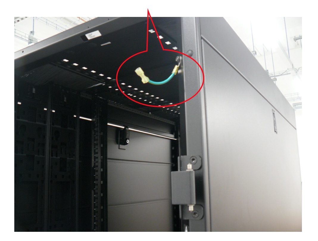
Re-install the front and rear doors. Ensure the earth cables are reconnected to the cable on the rack. Re-install the top and bottom side panels on each side of the rack.