3. Bow Pod DA configurations
It is possible to build a number of Bow Pod DA configurations, based on the different numbers of Bow-2000s, rack types and PDU types. Minimum requirements for the rack environment and PDUs are given in the next section. Fig. 3.1 and Fig. 3.2 illustrate the range of system configurations; others are also possible.
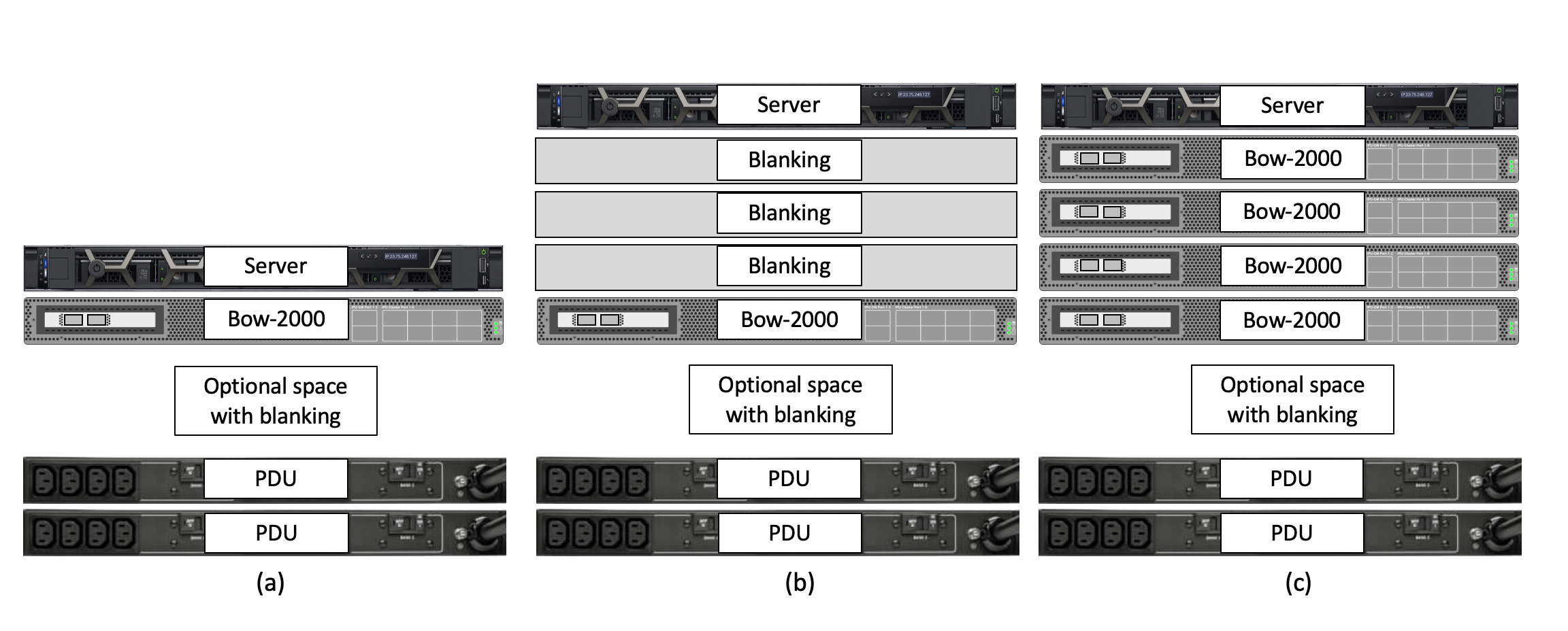
Fig. 3.1 Direct attach configurations (a-c)
System (a) is a baseline single Bow-2000 DA configuration, shown with redundant horizontally rack-mounted PDUs. System (b) is functionally the same Bow-2000 DA configuration where space has been allowed between the Bow-2000 and the server for future expansion up to a Bow Pod16 DA system. System (c) is a baseline Bow Pod16 DA configuration, with redundant horizontally rack-mounted PDUs. In all cases, power cabling to the PDUs can sometimes be made easier by allowing space between the lowest Bow-2000 and the PDUs.
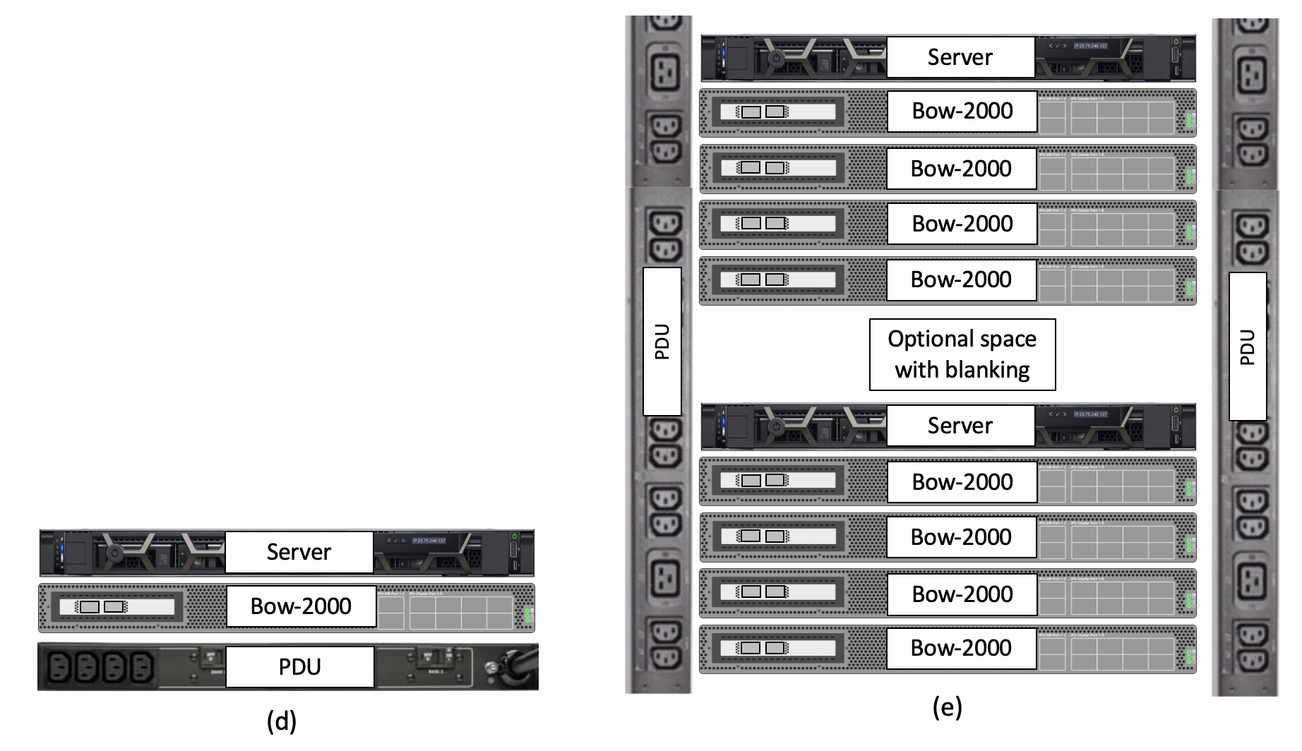
Fig. 3.2 Direct attach configurations (d-e)
Systems (d) and (e) show the extremes for a single Bow-2000 and Bow Pod16 DA configurations. System (d) is a minimally configured single Bow-2000 DA system using just one horizontally mounted PDU. While this is not recommended in production deployments due to lack of redundancy, it could be appropriate for small development systems. System (e) shows a larger rack deployment where more than one Bow Pod16 DA system is deployed. In this case, it may be more effective to use two higher power vertically mounted PDUs to supply more than one Bow Pod16 DA system. Given power and cooling, it is possible to build racks containing 4 or more Bow Pod16 DA systems powered by such vertical PDUs.