1. Overview
This guide is for properly trained service personnel and technicians who are required to install IPU-POD Direct Attach (DA) systems.
This guide covers IPU‑POD4 and IPU‑POD16 DA systems.
Warning
Only qualified personnel should install, service, or replace the equipment described in this document.
1.1. Acronyms and abbreviations
This is a short list that describes some of the most commonly used terms in this document.
Term |
Description |
AOC |
Active optical cable |
BMC |
Baseboard Management Controller. Standby power domain service processor doing system hardware management. |
BOM |
Bill of Materials |
GCD |
A graph compile domain is operated by a single poplar instance within the system, either for a single IPU-M2000 or for several IPU-M2000s connected by IPU-Link cables. |
GW-Link |
High speed (100 GbE) communication links that connect IPU-M2000s horizontally across IPU‑POD64 racks. Special cables are required for GW-Links. |
IPU-Gateway |
A device that disaggregates the server(s) and the four IPUs in the IPU-M2000 across a RoCE network, provides external IPU memory, and enables IPU scaleout across 100 GbE connections (GW-Links) for rack-to-rack connectivity. |
IPU-Link |
High speed communication links that connect IPUs both within and between IPU-M2000s in a Pod. Special cables are required for IPU-Links. |
PDU |
Power Distribution Unit |
RDMA |
Remote DMA |
RNIC |
RDMA Network Interface Controller |
RoCE |
RDMA over converged Ethernet |
ToR |
Top of Rack. Often also used as a term for the ToR RDMA switch that is placed on top of the IPU-M2000s. |
1.2. System summary
The IPU-M2000 is a 1 rack unit (RU) compute platform delivering 1 petaFLOPS (FP16.16) of AI compute. It contains 4 Colossus GC200 IPUs with 3.6GB In-Processor-Memory™ and is pre-configured with 128GB (2x64GB) Streaming Memory™, 1x 100GbE RoCEv2 NIC card for host server connectivity and 1TB of NVMe M.2 SSD. In addition, the IPU-M2000 has connectors for the IPU-Fabric™ that provide high speed interfaces (total 2.8Tbps) for connecting to other IPU-M2000s.
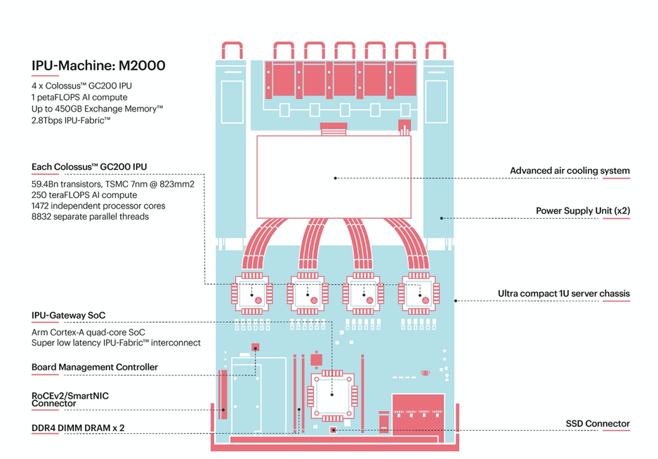
Fig. 1.1 IPU-Machine: M2000
An installed and fully operational IPU-POD DA system will consist of:
The IPU-POD Direct Attach AI compute platform
Configuration 1: IPU‑POD4 DA (single IPU-M2000 with 4 IPUs and a direct attached server)
Configuration 2: IPU‑POD16 DA (four IPU-M2000s with 16 IPUs and a direct attached server)
Additional options to be announced
Pre-installed and configured Virtual IPU (V-IPU) management software with embedded management through a web UI that offer easy installation and integration with pre-existing infrastructure
The Graphcore Poplar SDK software stack to be downloaded and installed on the host server
Approved host server pre-qualified by preferred channel partner
Please note that pre-integrated and qualified systems and integration support are available from channel partners.
An example IPU‑POD4 DA system is illustrated in Fig. 1.2.
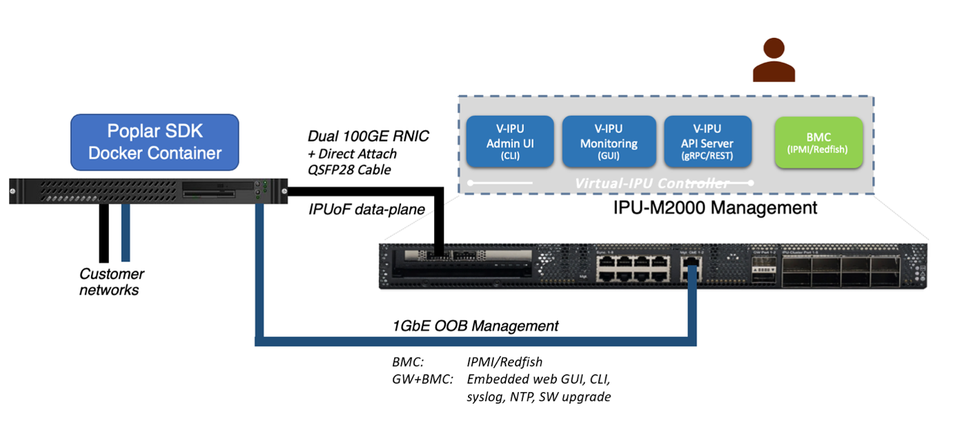
Fig. 1.2 IPU‑POD4 DA system
Both IPU-POD DA systems are fully supported by Graphcore’s Poplar® software development environment, providing a complete scalable platform for accelerated development. Existing ML frameworks such as TensorFlow, ONNX, and PyTorch are fully supported as well as industry standard converged infrastructure management tools including Open BMC, Redfish, IPMI, Docker containers, and orchestration with Slurm and Kubernetes. The PopVision™ visualisation and analysis tools provide monitoring of performance across one or more IPUs - the graphical analysis enables detailed inspection of all processing activities.
See the IPU-POD Direct Attach Getting Started Guide and the Poplar and PopLibs User Guide on the Graphcore documentation portal for details of Poplar installation and use.
Pictures of a complete IPU‑POD16 DA system are shown in Fig. 1.3 and Fig. 1.4.
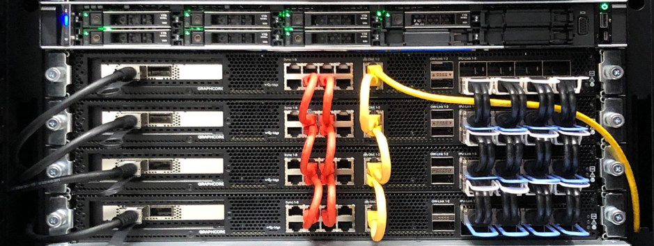
Fig. 1.3 Front view (cold isle)
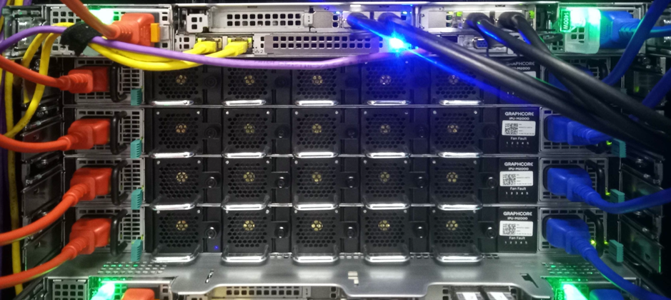
Fig. 1.4 Rear view (hot isle)
Note
Cable colours may differ.