Note: Searching from the top-level index page will search all documents. Searching from a specific document will search only that document.
Find an exact phrase: Wrap your search phrase in "" (double quotes) to only get results where the phrase is exactly matched. For example "PyTorch for the IPU" or "replicated tensor sharding"
Prefix query: Add an * (asterisk) at the end of any word to indicate a prefix query. This will return results containing all words with the specific prefix. For example tensor*
Fuzzy search: Use ~N (tilde followed by a number) at the end of any word for a fuzzy search. This will return results that are similar to the search word. N specifies the “edit distance” (fuzziness) of the match. For example Polibs~1
Words close to each other:~N (tilde followed by a number) after a phrase (in quotes) returns results where the words are close to each other. N is the maximum number of positions allowed between matching words. For example "ipu version"~2
Logical operators. You can use the following logical operators in a search:
+ signifies AND operation
| signifies OR operation
- negates a single word or phrase (returns results without that word or phrase)
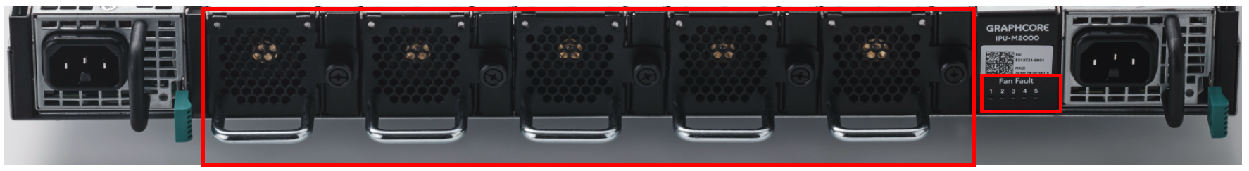
There are five fan modules at the rear of the IPU-Machine as shown in Fig. 3.1. There are also five LED indicators below the QR code that indicate if the fans are in a fault state.
Fig. 3.1 Fans and the fan fault indicators at the rear of the IPU-Machine.
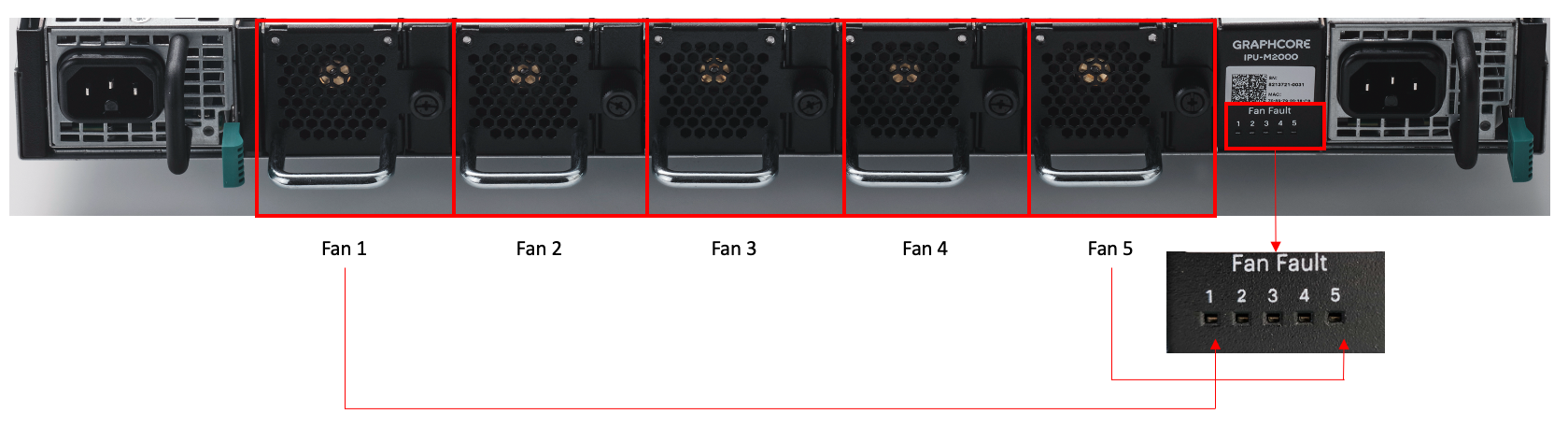
Each fan has a handle on the bottom and is attached to the IPU-Machine chassis by means of a knurled knob on the right.
Looking at the rear of the IPU-Machine, fans are numbered from left to right, starting from Fan 1 furthest on the left to Fan 5 furthest on the right (Fig. 3.2).
Information about the fans are also displayed when you run the BMC command ipum-utilsinventory_list. Refer to the Inventory monitoring section in the BMC User Guide for more information about this command and its output.
Note
In the BMC software, the numbering of the fan modules starts from 0. When looking at the rear of the IPU-Machine, fan 0 is the furthest left and fan 4 is the furthest right. The fan numbering in the hardware and the software is shown in Fig. 3.3.
Fig. 3.3 Fan numbering in the output of the ipum-utilsinventory_list BMC command
Identify the faulty fan at the rear of the IPU-Machine.
Completely undo the knurled knob.
Depending on how tight the knob is, you may be able to do this with your fingers. If necessary, you can use a screwdriver (Philips PH1) to loosen the knob before undoing it with your fingers.
Remove the faulty fan.
Gently pull on the handle on the bottom of the fan to remove the module.
Warning
You should only remove one fan module at a time. The IPU-Machine requires that at least four fans are installed.
Install the replacement fan.
Slide the replacement fan into the empty fan slot.
Gently and firmly push the fan all the way in.
You will know that the connection has been made when the fan starts up.
Insert the knurled knob and tighten with your fingers until the fan module is secure in the IPU-Machine.
Check that the replacement fan is functional.
The fan fault indicator should be off.
Running the ipum-utilsinventory_list command should show true in both the Present and Functional columns for that fan.