6. Replacing an IPU-Machine in a Pod
These instructions describe how to replace an IPU-Machine in an otherwise functional Pod.
6.1. Diagnosing IPU-Machine problems
On the bottom right of the front of the IPU-Machine are a set of three LED indicators (Fig. 6.1, Fig. 6.2). When the warning LED in the middle is amber, this indicates that a service action is required.
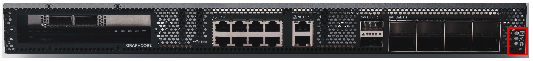
Fig. 6.1 Front LED indicators on the IPU-Machine.
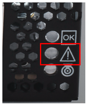
Fig. 6.2 When the warning LED (middle) is amber, this indicates that a service action is required.
There are many causes for the amber LED to light up. The details of the cause and what actions need to be taken are given in the system event log. You can access the system event log with the IPMI interface commands.
Note
Not all causes of the amber LED lighting up require the IPU-Machine to be replaced. If the IPU-Machine needs to be replaced, then follow the procedure described from Section 6.2, Ordering a replacement IPU-Machine to Section 6.8, Confirming replacement.
If you need additional help with troubleshooting problems with an IPU-Machine, contact Graphcore Support.
6.2. Ordering a replacement IPU-Machine
See Section 2, Ordering spare or replacement parts for how to order a replacement IPU-Machine.
6.3. Tools needed for the replacement
You need the following to replace an IPU-Machine in a Pod:
A server lift or another person if you do not have a server lift.
6.4. Unplugging cables
From the rear of the IPU-Machine, disconnect both power cables.
From the front of the IPU-Machine, disconnect all cables connecting the faulty IPU-Machine to neighbouring IPU-Machines and to the host server.
6.5. Removing an IPU-Machine from a Pod
To remove an IPU-Machine from the rack:
Prepare an appropriate server lift and adjust the height such that it is suitable for the IPU-Machine sliders. If a lift is not available, then this is a two-person operation.
Unscrew the captive thumb screws at the front of both the inner rack rails (Fig. 6.3).

Fig. 6.3 Remove the thumb screws at the front
Completely slide out the IPU-Machine on the rails.
Pull on the white tabs (Fig. 6.4) on both sides of the IPU-Machine to release it. Pull the IPU-Machine forwards until it starts sliding out of the outer rails.
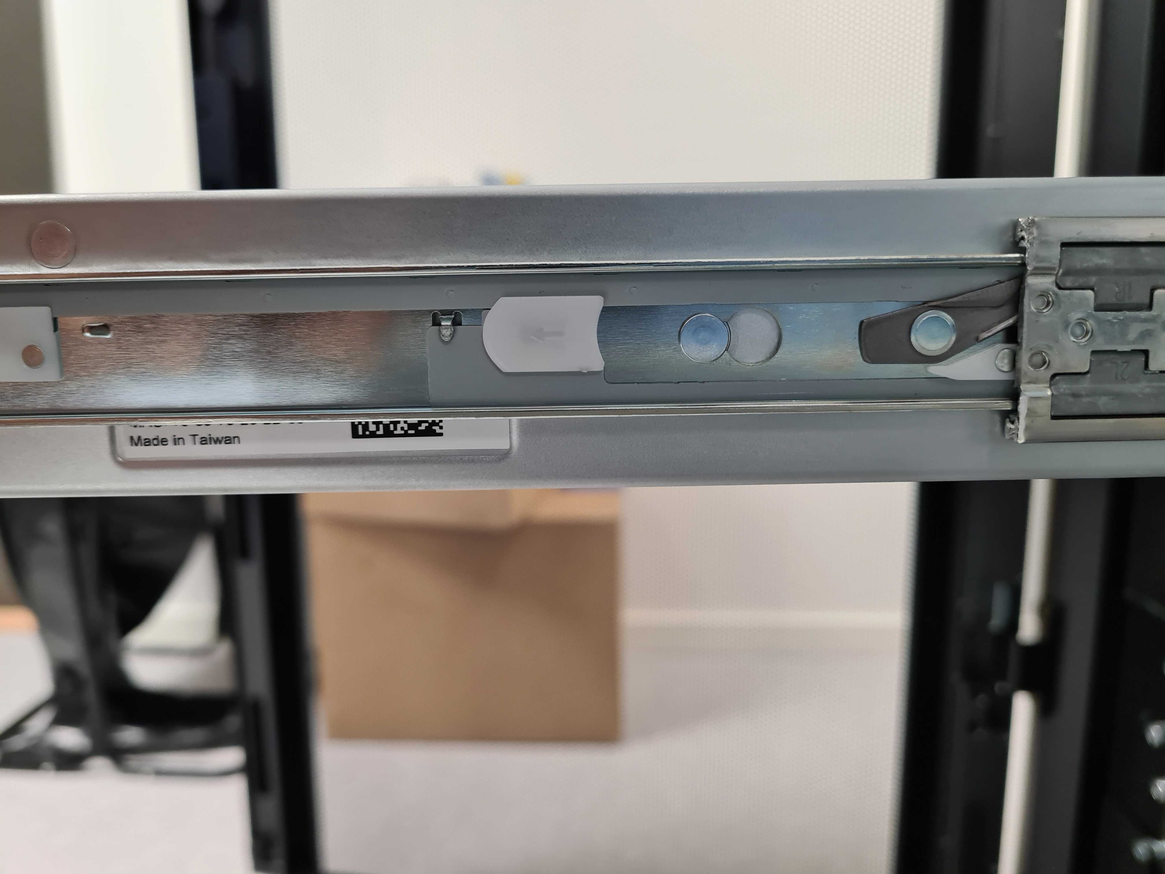
Fig. 6.4 Location of white release tab
Slide the IPU-Machine onto the server lift, if available, or two people should carry the IPU-Machine.
6.6. Installing IPU-Machine
Pull the sliding rail located within the outer rack rail completely forward such that it locks into the fully extended position (Fig. 6.5).
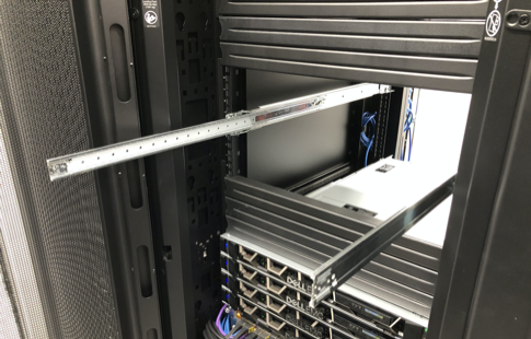
Fig. 6.5 IPU-Machine rack rail kit: sliders fully extended
Place the IPU-Machine onto an appropriate server lift and adjust the height such that it is suitable for the sliders (Fig. 6.6). If a lift is not available, this is a two person operation.
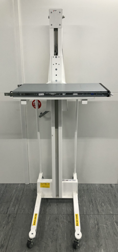
Fig. 6.6 Server lift for IPU-Machine
Slide the protruding inner rails (on the IPU-Machine) into the receiving channel of the extended outer rails (Fig. 6.7).
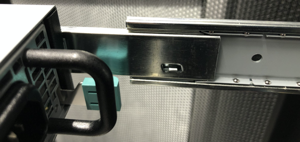
Fig. 6.7 Slide IPU-Machine inner rails into outer rails
Whilst the server lift is supporting the full weight of the IPU-Machine (or with two people carrying the IPU-Machine if not using a server lift), slide the IPU-Machine into the extended outer rails until you feel both sides engage a stopping mechanism (Fig. 6.9).
Then, simultaneously pull on the blue tabs for the release mechanism at each side of the IPU-Machine and then push the IPU-Machine unit fully into the rack (Fig. 6.8 and circled in Fig. 6.9).
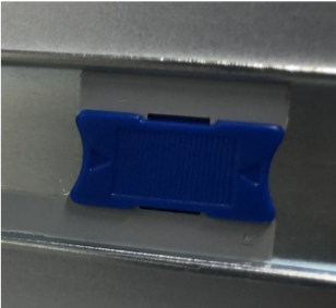
Fig. 6.8 Blue tab release mechanism
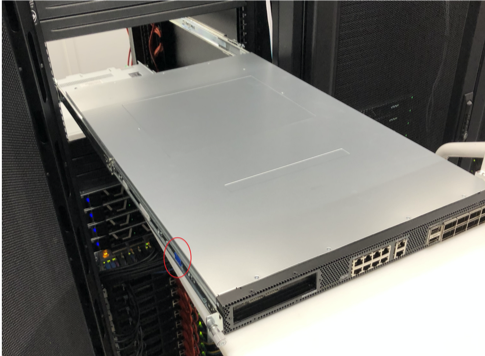
Fig. 6.9 Location of blue tab release mechanism
Finally, screw the captive thumb screw into the inner rack rail. (Fig. 6.10).
Fig. 6.10 Re-attach the IPU-Machine to the inner rack rail by tightening the captive thumb screws”
The IPU-Machine is now installed.
6.7. Connecting cables
On the front of the IPU-Machine, plug in all necessary cables to connect the replacement IPU-Machine to neighbouring IPU-Machines and to the host server.
Refer to the build and test guide for your Pod for more details of how to connect the cables.
Connect both the power cables to the rear of the IPU-Machine.
6.8. Confirming replacement
Confirm that the amber warning light on the front of the IPU-Machine is not lit.