6. Clusters
6.1. Overview
A typical data centre V-IPU deployment needs to manage many IPUs that are distributed among multiple IPU-Machines located in one or more Pod racks. To accommodate flexible scaled-out cluster installations and achieve separation of concerns for administrative as well as user needs, V-IPU implements the different Cluster entities and Cluster topologies that are described in this chapter.
6.2. Cluster entities
A cluster entity represents a logical group of non-overlapping hardware resources that are controlled by a V-IPU controller. Cluster entities are hierarchical, requiring certain system components (mainly hardware) or other entities to be in place.
Three main cluster entities exist, as shown in Fig. 6.1 and explained in the rest of this section: agent, cluster and partition.
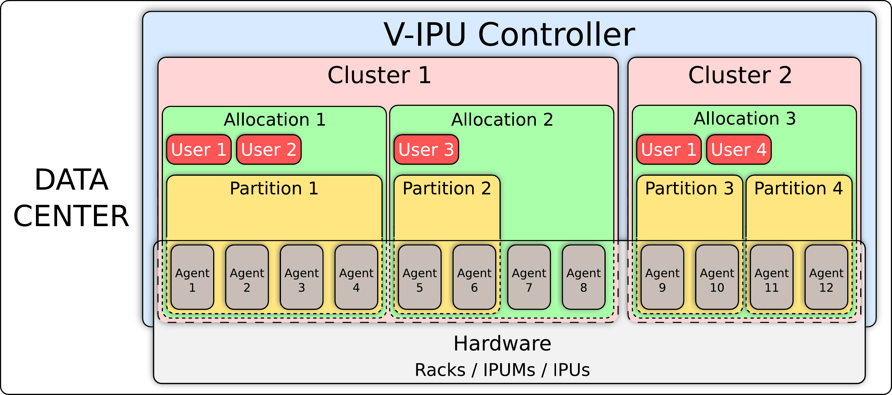
Fig. 6.1 Conceptual representation of agent, cluster and partition entities
6.2.1. Agent entity
The agent entity represents a V-IPU agent. There is a one-to-one mapping of agents to IPU-Machines.
To create an agent entity, you need to specify a unique agent identifier, as well as the hostname (or IP address) and port number of the gateway management interface that the agent listens to. These addresses will have been assigned when the Pod was configured.
You can create an agent entity using the create agent command.
For example, the following command creates an agent entity with the identifier “ag1” and
listening to 10.1.2.1:8080:
$ vipu-admin create agent ag1 --host 10.1.2.1 --port 8080
create agent (ag1): success.
Agent auto-discovery
The V-IPU software has an auto-discovery option for finding agents. This is only
available if it has been explicitly enabled using the
--autodiscovery-listen-interfaces (-a) option to the V-IPU controller
(see Section 10.1, Global options).
To list all the agents that are discovered, use the command:
$ vipu-admin discover agent
Host        | Port | Network Interface | Time Since Last Seen | Agent Auto-Add ID
-----------------------------------------------------------------------------------
10.1.2.1    | 8081 | eno3              | 2.154768458s         | 10.1.2.1-8080
10.1.2.2    | 8080 | eno3              | 4.741639744s         | 10.1.2.2-8080
-----------------------------------------------------------------------------------
You can also use the command to automatically add the agents that are discovered:
$ vipu-admin discover agents --auto-add
Added agent 10.1.2.1-8080
Added agent 10.1.2.2-8080
This will add all those agents as elements in the controller. The auto-generated agent names are of the form “IP-port”. For example, if an agent is discovered at 10.1.2.1:8080, the auto-generated agent ID will be “10.1.2.1-8080”.
The agents multicast their presence every 5 seconds. If you start the
controller with vipu-server -a eth0,eth1 the controller will listen for these
multicast messages on the eth0 and eth1 network interfaces.
6.2.2. Clusters
The cluster entity groups a set of agents and forms an isolated logical cluster. Therefore, a minimum of one agent entity is required to create a cluster entity.
A cluster is the foundation for managing a set of IPU-Machines and verifying deployment correctness (see Section 6.4, Cluster tests) before making them available to end-users for running applications.
To create a cluster, you need to specify a unique cluster identifier, as well as a list of agent identifiers. You must list these in the order that reflects the physical network topology.
Since a cluster spans multiple agents, the V-IPU controller needs to be aware of the expected physical network topology: how the different IPU-Machine ports (sync ports, cluster ports and IPU gateway ports) are connected to other IPU-Machines (see Section 6.3, Cluster topologies for supported cluster topologies).
As illustrated in Fig. 6.1, a V-IPU controller can control one or more independent clusters. However, note that an agent can only participate in one cluster.
Assuming there are four agents with agent identifiers “ag1”, “ag2”, “ag3”,
and “ag4”, you can create a cluster using the create-cluster command as
shown:
$ vipu-admin create cluster cl0 --agents ag1,ag2,ag3,ag4
create cluster (cl0): success.
Note
When creating a cluster, the agents must correspond to IPU-Machines that are physically consecutive in the rack. They must be specified in order, starting from the one lowest in the rack.
For a complete reference to the create cluster command please refer to Section 9, Admin command line reference.
IPU-Link Domains
A IPU-Link Domain (ILD) represents a subset of IPUs in the cluster that are connected by IPU-Links, that is, with one-dimensional connectivity. When a cluster has more than one ILD, the connections between them are made by using the GW-Links.
An ILD is a core entity used to represent multi-dimensional scale-out out Cluster topologies.
To see the number of ILDs and the IPU-Link topology, you can use
the get cluster command.
An example of output from the get cluster command for a cluster named “cl0” is shown below:
$ vipu-admin get cluster cl0
-----------------------------------------------------------------
  Cluster                   | cl0
  GW-Link topology          | LOOPED
  Number of ILDs            | 1
  IPU-Link Topology         | MESH
  Number of IPUs            | 8
  IPUs                      | ILD 0
                            | 0=ag1:0 1=ag1:1 2=ag1:2 3=ag1:3
                            | 4=ag2:0 5=ag2:1 6=ag2:2 7=ag2:3
-----------------------------------------------------------------
Refer to the create cluster command in Section 9, Admin command line reference
for details about how to choose the number of ILDs and the
IPU-Link topology when creating a new cluster.
6.2.3. Allocation
An allocation entity makes IPU-Machines available to create partitions. Therefore, a cluster must have at least one allocation in order to create partitions in it. The IPU-Machines in an allocation must come from a single cluster. Each IPU-Machine can only be assigned to one allocation.
To create an allocation in a cluster, you need to specify a unique allocation identifier, as well as the cluster identifier and the size of the allocation.
Note
When creating an allocation in a cluster, the V-IPU controller allocates IPU-Machines that are physically consecutive in the rack.
For a complete reference to the create allocation command please refer to Section 9, Admin command line reference.
6.2.4. Partition
The partition entity provides a set of available IPUs from an allocation in a cluster. It is the top level entity that end users request, in order to run an application on IPUs.
An allocation is required in order to create partition entities. Partitions are discussed in detail in the Virtual-IPU User Guide.
6.3. Cluster topologies
A V-IPU cluster topology represents the arrangement of the IPUs and network links (IPU-Links, GW-Links, and Sync-Links). Clusters are of two main types:
Single-ILD clusters: IPUs in single-ILD clusters are connected using IPU-Links arranged in a particular topology.
The synchronisation network formed by the Sync-Links is also contained within the ILD.
Multi-ILD clusters: A multi-ILD cluster, as the name suggests, consists of multiple domains.
A multi-ILD cluster topology is created by the GW-Links between the constituent domains. The IPUs in each ILD are connected according to the IPU-Link topology as with a single ILD cluster.
The synchronisation network spanning multiple domains uses the GW-Links.
6.3.1. IPU-Link topologies
In this section, we describe the available topologies for connecting IPU-Links within an ILD.
The V-IPU management software supports two types of IPU-Link topologies: “mesh” and “torus”.
Mesh
In a mesh topology, IPUs are connected so that the cables that connect pairs of IPUs do not cross over one another. The resulting topology is like a ladder, where the rails of the ladder are formed by links between the pairs of IPUs, and the rungs are formed by the links between the IPUs in each pair.
An example ILD consisting of four IPU-Machines with mesh topology is shown in Fig. 6.2. Note that, for simplicity, we do not show Sync-Links.

Fig. 6.2 An example mesh topology with four IPU-Machines
The IPU-Link and Sync-Link cabling of a single-ILD cluster with eight IPU-Machines in mesh topology is shown in Fig. 6.3.
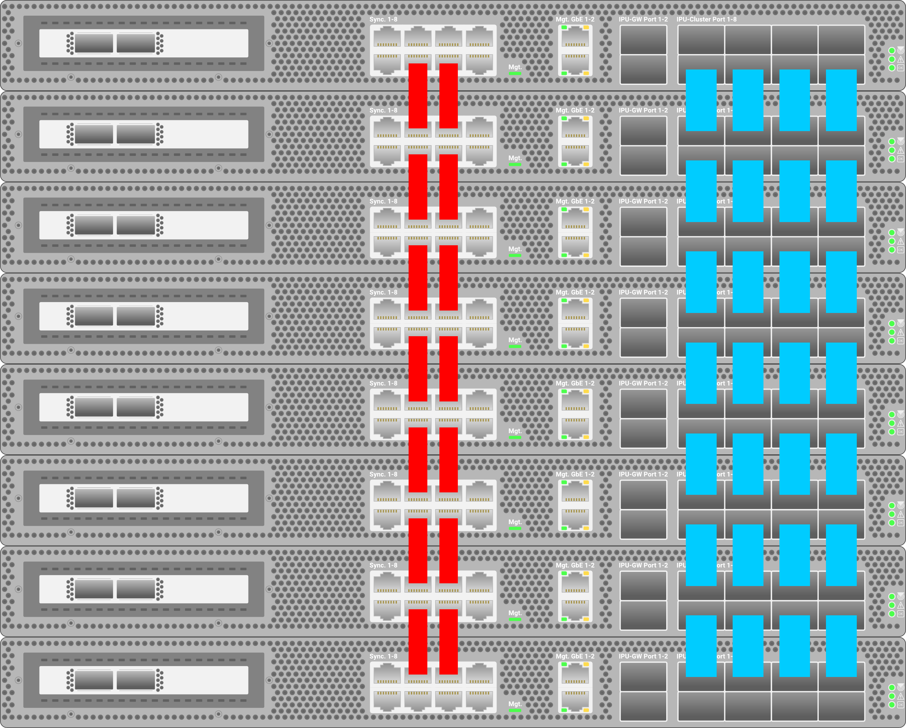
Fig. 6.3 IPU-Link (blue) and Sync-Link (red) cabling for a single-ILD mesh cluster
You can create a cluster with mesh topology using the create cluster command.
For example:
$ vipu-admin create cluster mymesh --topology mesh --agents ag1,ag2
Torus
Torus topology is similar to a mesh topology except that the IPU-Links between the first and the last IPU-Machines are connected in a loop-back manner.
An example ILD consisting of four IPU-Machines with torus topology is shown in Fig. 6.4.

Fig. 6.4 An example torus topology with four IPU-Machines
The IPU-Link and Sync-Link cabling of a single-ILD cluster with eight IPU-Machines in torus topology is shown in Fig. 6.5.
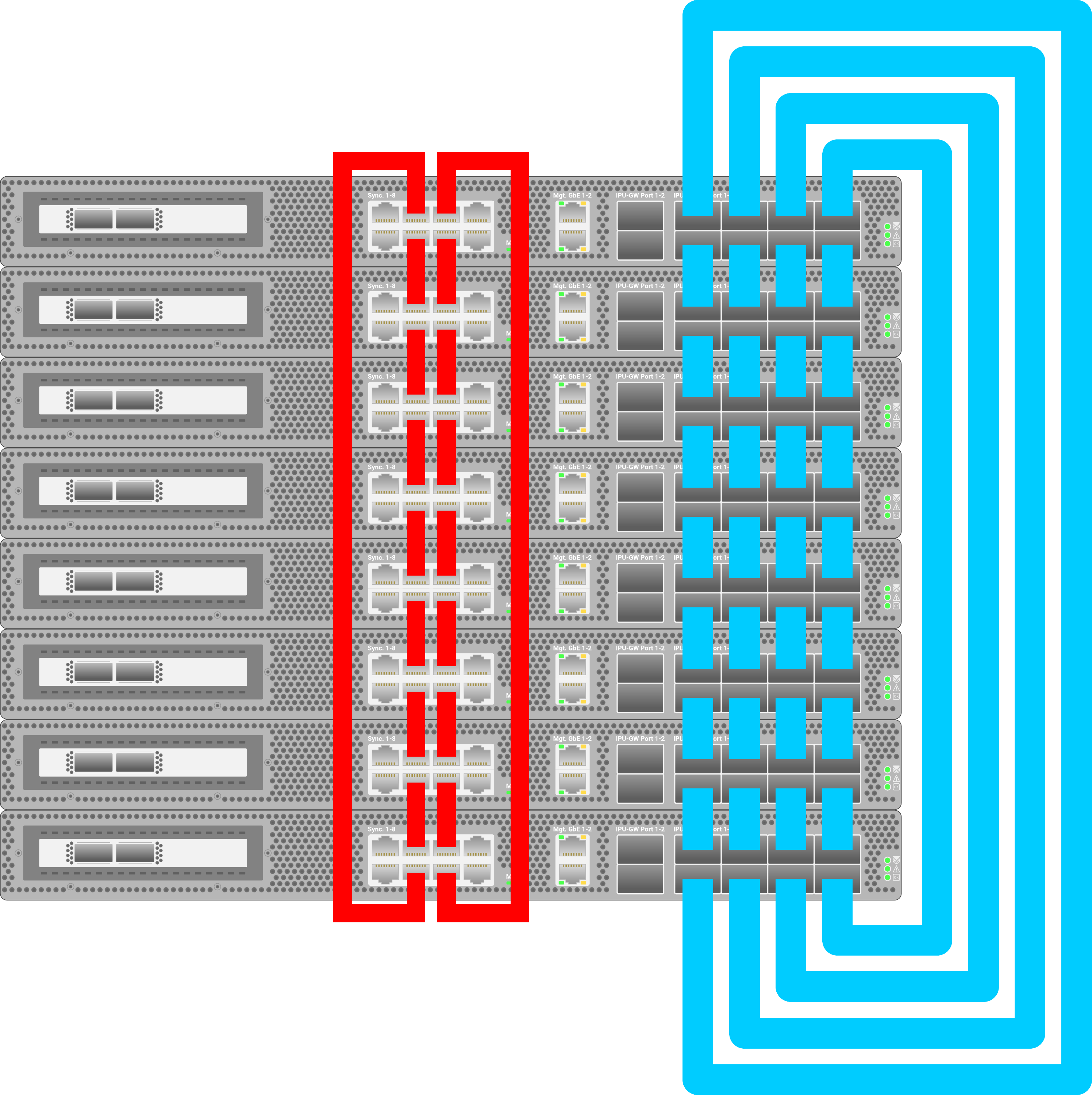
Fig. 6.5 IPU-Link (blue) and Sync-Link (red) cabling for a single-ILD torus cluster
You can create a cluster with torus topology using the create cluster command. For example:
$ vipu-admin create cluster mytorus --topology torus --agents ag1,ag2
6.3.2. GW-Link topologies
Two topologies for connecting GW-Links are supported: “looped” and “switched”.
Looped
In a looped topology, each IPU-Machine is connected with its right GW-Link to the corresponding IPU-Machine in the ILD on its right, while its left GW-Link is connected to the right link of the corresponding IPU-Machine in the ILD on its left. Additional GW-Links connect the corresponding IPU-Machines in the first and the last domains of the cluster.
The cabling of an example looped GW-Link cluster is shown in Fig. 6.6.
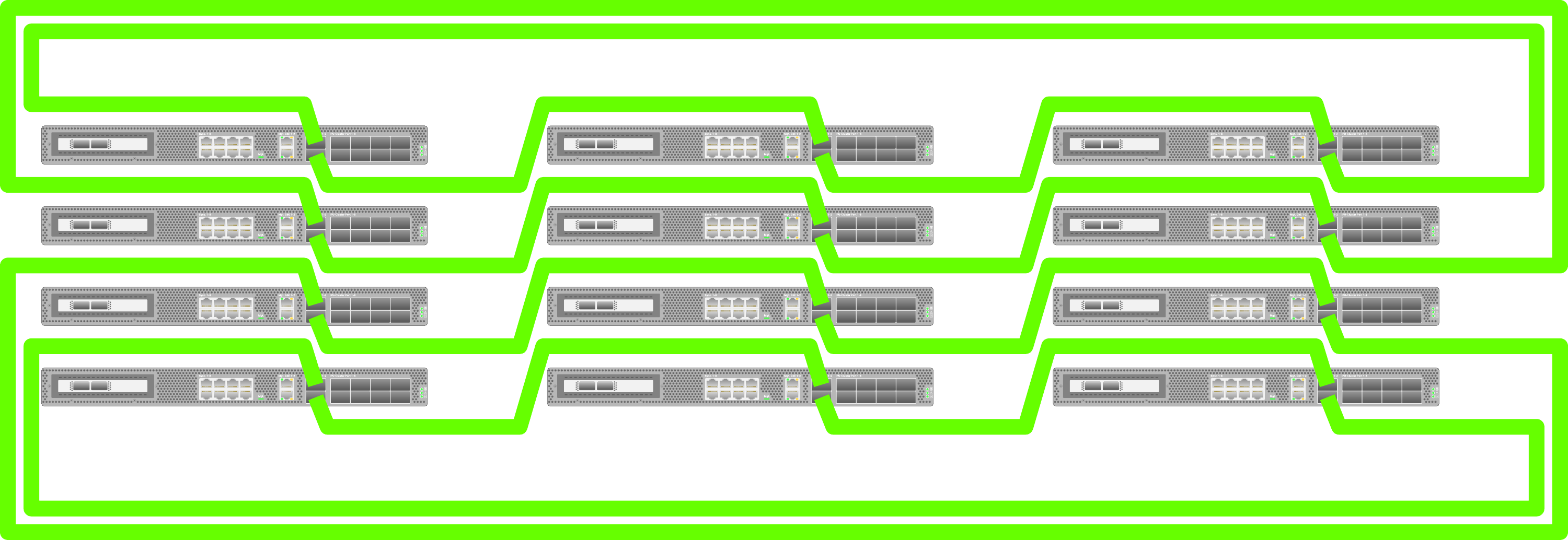
Fig. 6.6 Cabling for a multi-ILD looped cluster
You can create a cluster with looped topology by providing the --cluster-topology option to
the vipu-admin command:
$ vipu-admin create cluster loopedMeshesCluster --num-ipulinkdomains 3 --topology mesh --cluster-topology looped --agents ag1,ag2,ag3,ag4,ag5,ag6,ag7,ag8,ag9,ag10,ag11,ag12
$ vipu-admin create cluster loopedTorusCluster --num-ipulinkdomains 3 --topology torus --cluster-topology looped --agents ag1,ag2,ag3,ag4,ag5,ag6,ag7,ag8,ag9,ag10,ag11,ag12
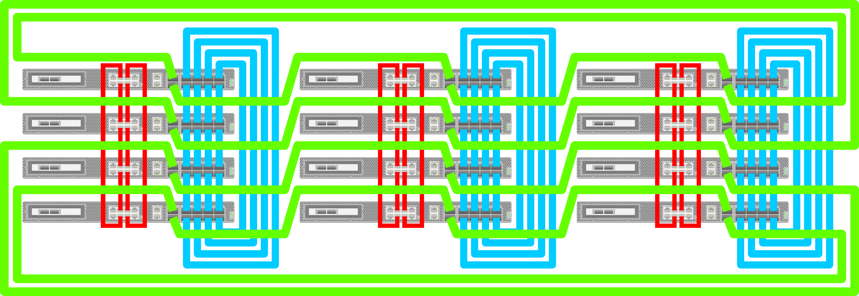
Fig. 6.7 Complete cabling in a cluster (looped) with three domains, four IPU-Machines per ILD (torus)
Switched
In a switched topology, each GW-Link is connected to a network switch. Note that all of the links must be connected to the same switch. This differs from the looped topology where the GW-Link cables between the IPU-Machines are directly connected.
An example of the cabling in a switched GW-Link cluster is shown in Fig. 6.8.
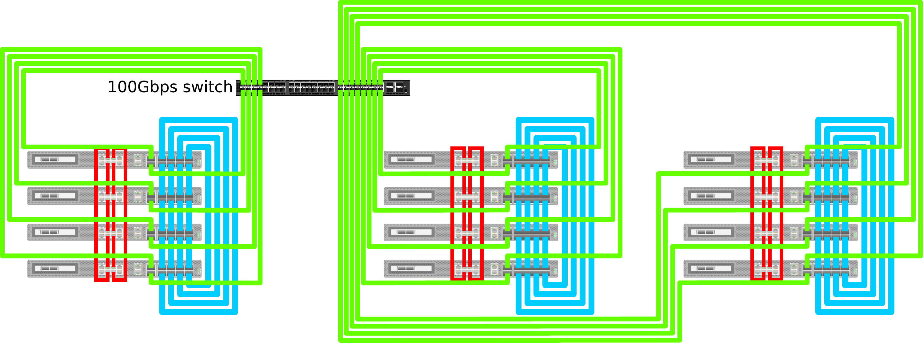
Fig. 6.8 Cabling for a multi-ILD switched cluster
Switched topology clusters can be created by setting the --cluster-topology option to switched
when using the vipu-admin command:
$ vipu-admin create cluster switchedMeshesCluster --num-ipulinkdomains 3 --topology mesh --cluster-topology switched --agents ag1,ag2,ag3,ag4,ag5,ag6,ag7,ag8,ag9,ag10,ag11,ag12
$ vipu-admin create cluster switchedTorusCluster --num-ipulinkdomains 3 --topology torus --cluster-topology switched --agents ag1,ag2,ag3,ag4,ag5,ag6,ag7,ag8,ag9,ag10,ag11,ag12
6.4. Cluster tests
The V-IPU controller contains a cluster testing suite that runs a series of tests to verify installation correctness. You can execute a cluster test against a cluster entity before any partitions are created. It is strongly recommended that you run all the test types provided by the cluster testing suite before deploying any applications in a cluster.
Assuming you have created a cluster named “cl0” formed by four agents
with the command create cluster cl0 --agents ag1,ag2,ag3,ag4, the simplest
way to run a complete cluster test for this cluster is by using the test
cluster command, as shown below:
$ vipu-admin test cluster cl0
Showing test results for cluster cl0
Test Type | Duration | Passed | Summary
---------------------------------------------------------------------------
Sync-Link | 153.96s | 14/14 | Sync Link test passed
Cabling | 12.02s | 28/28 | All cables connected as expected
IPU-Link | 7.39s | 156/156 | All Links Passed
Traffic | 156.71s | 3/3 | Traffic test passed
GW-Link | 0.00s | 0/0 | GW Link test skipped
Version | 0.01s | 6/6 | All component versions are consistent
---------------------------------------------------------------------------
As the test results show, six test types were executed on cluster “cl0”. The results for each test type are printed one per line in the output. Each test type tested zero or more elements of the cluster as can be seen from the “Passed” column. Each test type is explained in detail in the rest of this section.
Note that the command executed in the snippet above blocks the command until the
cluster test is completed, and this particular test took more than five minutes to
complete. For larger clusters it might take even longer. To avoid blocking the
command for prolonged periods of time, you can execute cluster tests asynchronously
with the --start, --status and --stop options, as follows:
$ vipu-admin test cluster cl0 --start
# Launches an async cluster test and command returns immediately
# User can run any other commands here...
# Checks the status of the cluster test while a test is running
$ vipu-admin test cluster --status
test cluster (status): failed: No results available. Test in cluster cl0 is in progress.
# Fetch the results of the last test executed
$ vipu-admin test cluster --status
Showing test results for cluster cl0
Test Type | Duration | Passed | Summary
---------------------------------------------------------------------------
Sync-Link | 0.84s | 14/14 | Sync Link test passed
Cabling | 12.02s | 28/28 | All cables connected as expected
IPU-Link | 7.39s | 156/156 | All Links Passed
Traffic | 156.71s | 3/3 | Traffic test passed
GW-Link | 0.00s | 0/0 | GW Link test skipped
Version | 0.01s | 6/6 | All component versions are consistent
---------------------------------------------------------------------------
# Interrupt a cluster test with the stop command
$ vipu-admin test cluster cl0 --start
$ vipu-admin test cluster --stop
$ vipu-admin test cluster --status
test cluster (status): failed: No results available. Last test in cluster cl0 was stopped.
When a cluster test is running, some restrictions are imposed on the actions an administrator can perform on the system:
Partition creation in a cluster where a test is in progress is forbidden.
Removal of a cluster where a test is in progress is forbidden.
Only one cluster test can be running at any given time on a V-IPU controller, even if the V-IPU controller controls more than one cluster.
There is no persistence of the cluster test results. Only the results of the last test can be retrieved with the
--statuscommand, as long as the V-IPU controller has not been restarted.
6.4.1. List of cluster tests
Sync test
The sync test verifies the external Sync-Link cabling that connects IPU-Machines in the same IPU-Link domain together,
in addition to verifying sync over GW-Links between domains.
You can run a sync test by passing the --sync option to the test
cluster command. The output of a passing test will be similar to that shown below:
$ vipu-admin test cluster cl0 --sync
Showing test results for cluster cl0
  Test Type   | Duration | Passed | Summary
---------------------------------------------------------
  Sync-Link   | 0.93s    | 14/14  | Sync Link test passed
---------------------------------------------------------
The cluster tested above is a single-ILD topology with eight V-IPU agents (eight IPU-Machines). As seen in Fig. 6.3, this topology consists of 14 Sync-Link cables, and all of the Sync-Link cables have passed the test.
In cluster topologies that span across multiple domains, such as the one in Fig. 6.6, the sync test also tests the synchronisation over the GW-Link cables that span between domains.
A sync test failure reports the cables that failed to satisfy the cluster topology that is being tested by listing the agents and Sync-Link port enumeration of the failing Sync-Links. In the example command below, two Sync-Link$2 cables between “ag1” and “ag2” fail:
the link between “ag1” Sync-Link port 6 and “ag2” Sync-Link port 2
the link between “ag1” Sync-Link port 7 and “ag2” Sync-Link port 3
This is an indication of either faulty cabling or an incorrect cluster definition.
Fig. 6.9 shows the Sync-Link port enumeration in an IPU-Machine:
$ vipu-admin test cluster cl0 --sync
Showing test results for cluster cl0
  Test Type   | Duration | Passed | Summary
------------------------------------------------------
  Sync-Link   | 0.90s    | 12/14  | Failed Sync Links:
              |          |        | ag1:6 <--> 2:ag2
              |          |        | ag1:7 <--> 3:ag2
------------------------------------------------------
test (cluster): failed: Some tests failed.
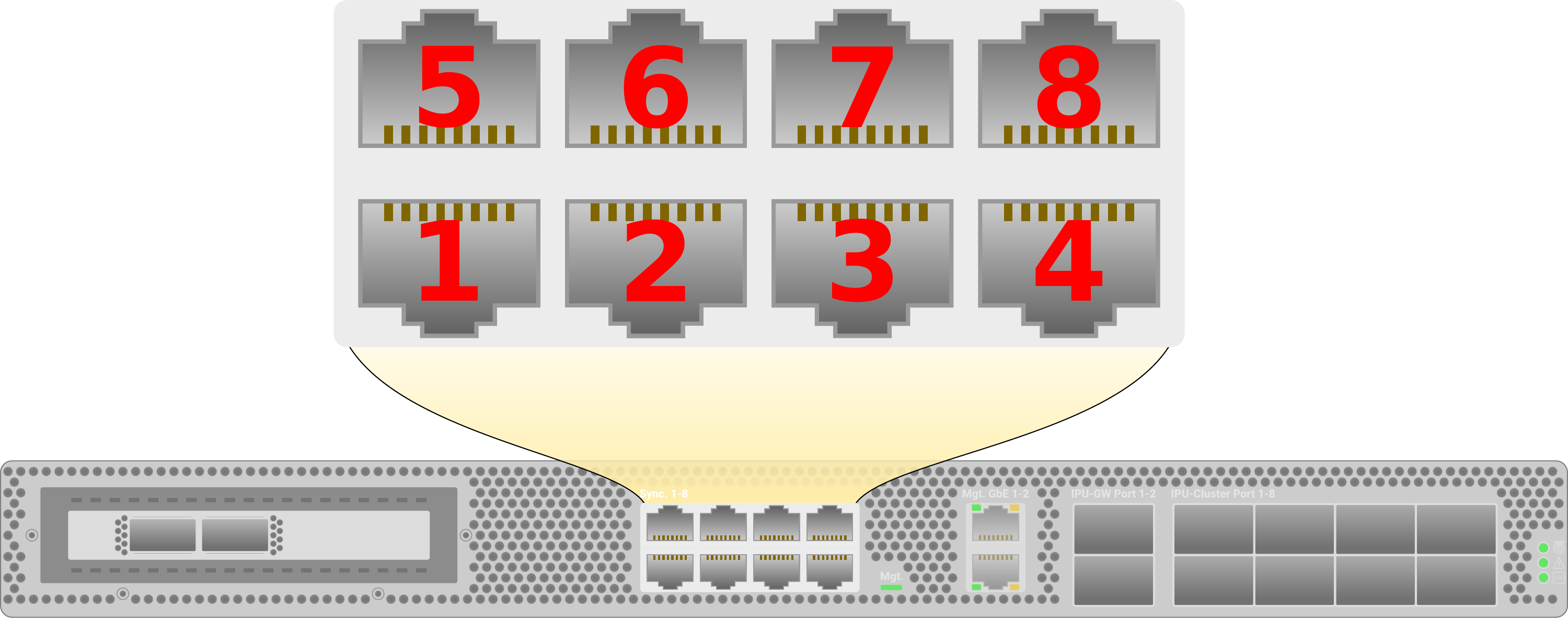
Fig. 6.9 IPU-Machine Sync-Link port enumeration
IPU-Link training test
The IPU-Link training test verifies IPU-Link readiness (for IPU-Links within an IPU-Machine)
and correct cluster link cabling (IPU-Links between IPU-Machines) based on the topology
of the ILD that an IPU is part of. You can run an IPU-Link test
with the --ipulink option in the test cluster command. The
output of a passing IPU-Link test is shown below:
$ vipu-admin test cluster cl0 --ipulink
Showing test results for cluster cl0
  Test Type   | Duration | Passed  | Summary
-----------------------------------------------------
  IPU-Link    | 12.42s   | 156/156 | All Links Passed
-----------------------------------------------------
In the example test run above, a cluster formed by eight agents (eight IPU-Machines) in mesh topology, as illustrated in Fig. 6.3, has been tested and all 156 IPU-Links passed the test. Note that, although in Fig. 6.3 with eight IPU-Machines we only have 28 cluster links, the IPU-Link test tests all IPU-Links for readiness, including the internal IPU-Links. As such, 156 IPU-Links are tested.
A failing test will indicate which IPU-Links are failing by identifying the agent and cluster port enumeration of the failing IPU-Link. In the following example, a cluster with an expected ILD in torus topology (see Fig. 6.5) is tested, but the four cluster links that form the torus loop (cables from bottom to top of the ILD) fail:
$ vipu-admin test cluster cl0 --ipulink
Showing test results for cluster cl0
  Test Type   | Duration | Passed  | Summary
-------------------------------------------------------------------------------------
  IPU-Link    | 34.57s   | 156/160 | Failed Links
              |          |         | #ag1:4 [pending g1x1] <--> #ag8:8 [pending g1x1]
              |          |         | #ag1:3 [pending g1x1] <--> #ag8:7 [pending g1x1]
              |          |         | #ag1:1 [pending g1x1] <--> #ag8:5 [pending g1x1]
              |          |         | #ag1:2 [pending g1x1] <--> #ag8:6 [pending g1x1]
-------------------------------------------------------------------------------------
test (cluster): failed: Some tests failed.
Fig. 6.10 shows the cluster port enumeration in an IPU-Machine. Note that in the case where an IPU-Link fails internally in an IPU-Machine, the failed port enumeration will not match that of Fig. 6.10.
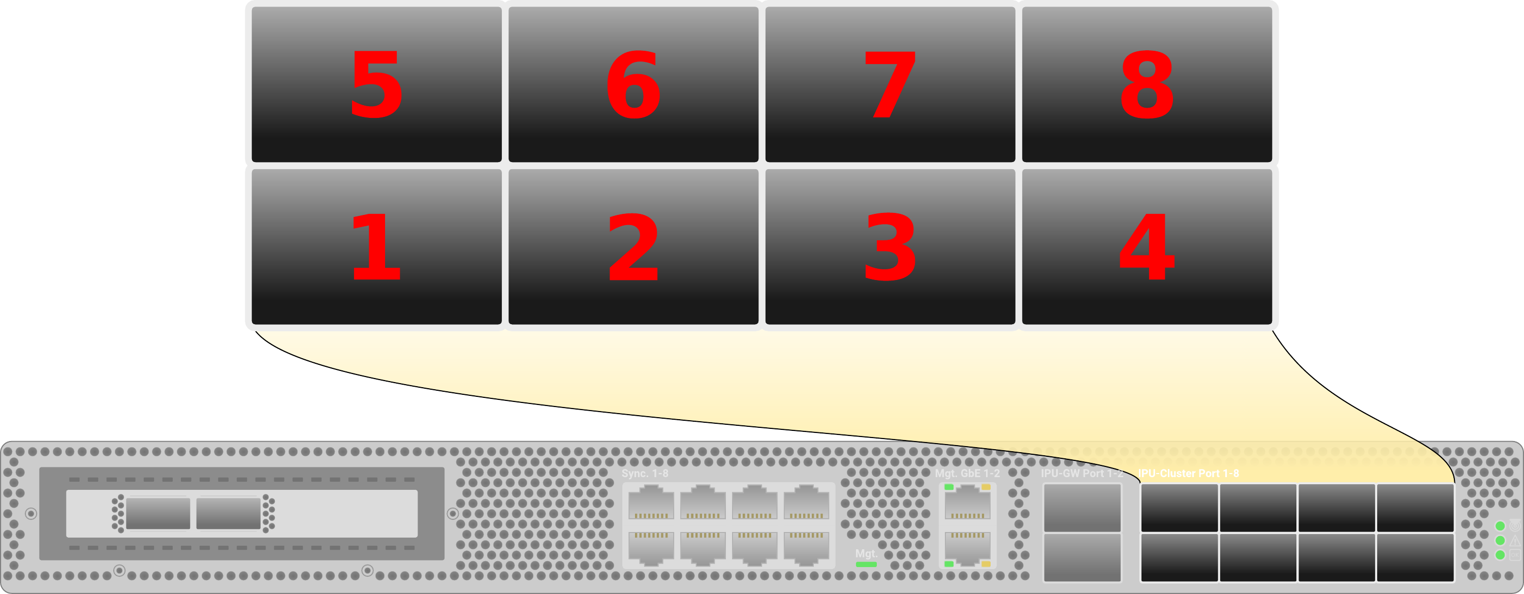
Fig. 6.10 IPU-Machine cluster port enumeration
Traffic test
The traffic test acts as a smoke test within all domains (GW-Links are not used by the traffic test, see GW-Link traffic test for testing GW-Links) of a cluster before deploying applications. The test works by loading and running a simple IPU program on up to 16 IPUs inside each ILD. If the domains have more than 16 IPUs, multiple overlapping traffic tests will be executed in order to ensure that traffic is sent over all of the cluster links as shown in Fig. 6.11.
You can invoke the traffic test with the --traffic option. Note that for a
traffic test to pass, a prerequisite is that the Sync-Link and IPU-Link training
tests have passed first.
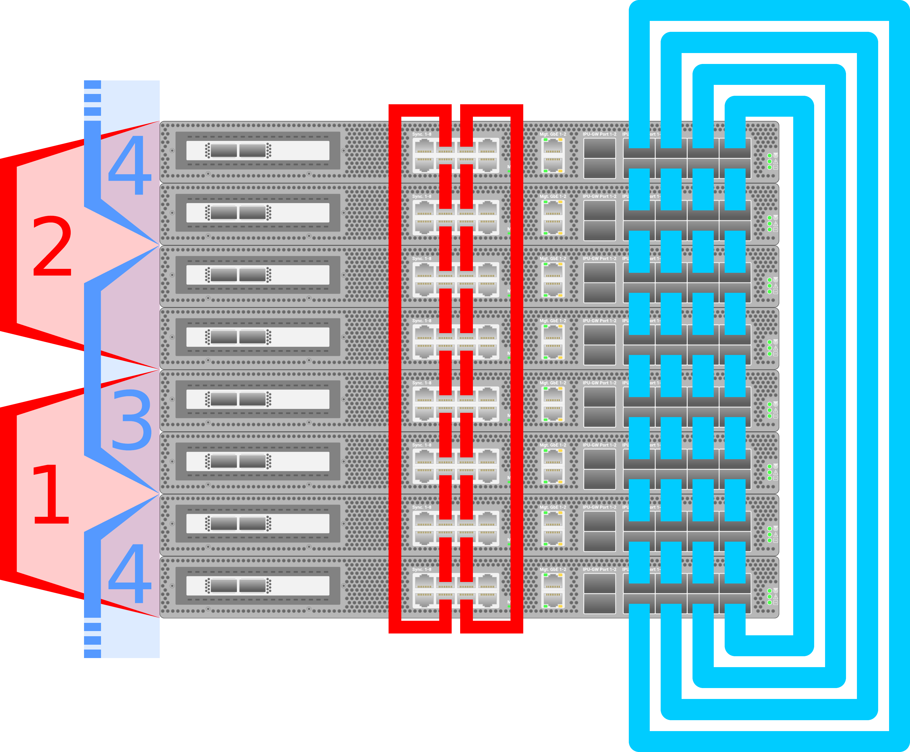
Fig. 6.11 Four overlapping traffic tests with IDs 1-4 will run in an ILD with eight IPU-Machines in torus topology
The traffic test can report corrected IPU-Link errors that can reveal potential cabling issues that are not captured by the IPU-Link and cluster link test as shown in the example output below:
$ vipu-admin test cluster cl0 --traffic
  Test        | Duration | Passed | Summary
----------------------------------------------------------------------------------------------------------
  Traffic     | 210.17s  | 0/1    | Traffic test failed
              |          |        | Errors encountered in traffic test 1
              |          |        | corrected link errors: 838
              |          |        | - ag3:1 <--> ag2:5 (327)
              |          |        | - ag2:4 <--> ag1:8 (521)
----------------------------------------------------------------------------------------------------------
test cluster (cl0): failed: Some tests failed.
The index of the traffic test, for example traffic test 1 in the output above, refers to the traffic test ID for the overlapping tests (see Fig. 6.11).
Currently, the threshold for corrected errors per link is 300. That is, if a link reports more than 300 corrected link errors it qualifies as failure, otherwise it passes.
From the output above, it can be seen that two links reported more than 300 corrected link errors (327 and 521), and thus the test fails.
GW-Link traffic test
The GW traffic test verifies that communication over the GW-Links works as expected. The test works by splitting the cluster into pairs of IPU-Ms, connected by a single GW-Link, and sending packets across the connection. Similar to the traffic test, the GW traffic test acts as a smoke test and tests GW-Link functionality needed for regular operation. Examples include sync participation and packet transmission/reception.
In order to invoke the test, pass the --gw-traffic option. The test is currently not enabled by default.
Note that the GW traffic test requires a cluster with GW-Links in order to run, that is with 2 or more IPU-Link domains. Otherwise, the test will be skipped.
An example of a successful run for a cluster with 2 IPU-Link domains with 16 IPU-Ms each and looped cluster topology (32 GW-Link connections) is shown in the output below:
$ vipu-admin test cluster cl0 --gw-traffic
Showing test results for cluster cl0
  Test Type   | Duration | Passed | Summary
----------------------------------------------------------
  GW Traffic  | 62.38s   | 32/32  | GW Traffic test passed
----------------------------------------------------------
In case of failure, the failed GW-Link and the corresponding GW-Link ports will be listed.
The output below shows the results of testing on the cluster in Fig. 6.6 when the 2 GW-Links of the top row are not connected.
In this particular example, the output specifies that the GW-Links that failed are between agA4 (top IPU-M in the 1st IPU-Link domain) GW-Port 1 and
agB4 (top IPU-M in the 2nd IPU-Link domain) GW-Port 2, as well as between agB4 GW-Port 1 and agC4 (top IPU-M in the 3rd IPU-Link domain) GW-Port 2.
For GW-Port chassis enumeration, see Fig. 6.12.
$ vipu-admin test cluster cl0 --gw-traffic
Showing test results for cluster cl0
  Test Type   | Duration | Passed | Summary
---------------------------------------------------------------------------------------
  GW Traffic  | 72.56s   | 10/12  | GW Traffic test failed
              |          |        | Error during gwtraffic test for agA4:1 -- agB4:2
              |          |        | 1 gateway link(s) couldn't be brought up
              |          |        | Error during gwtraffic test for agB4:1 -- agC4:2
              |          |        | 1 gateway link(s) couldn't be brought up
---------------------------------------------------------------------------------------
GW-Link test
The GW-Link test verifies GW-Link cabling that is only present in multi-ILD
cluster topologies (see Section 6.3, Cluster topologies). You can invoke a
GW-Link test by passing the --gwlink option to the test cluster
command. The output of a passing test can be seen in the example below:
$ vipu-admin test cluster cl0 --gwlink
Showing test results for cluster cl0
  Test Type   | Duration | Passed | Summary
-------------------------------------------------------
  GW-Link     |  9.79s   | 12/12  | GW Link test passed
-------------------------------------------------------
The test executed in this example tested the topology presented in Fig. 6.6, where three domains with four IPU-Machines per ILD form a cluster in looped cluster topology with 12 GW-Link cables.
A failed test will report the links that cannot be brought up. The IPU-GW port enumeration of an IPU-Machine that is presented in Fig. 6.12 can be used to identify the misbehaving links:
$ vipu-admin test cluster cl0 --gwlink
Showing test results for cluster cl0
  Test Type   | Duration | Passed | Summary
--------------------------------------------------------------------------
  GW-Link     |  9.66s   | 11/12  | Failed GW Links:
              |          |        | (down) ag1:2 <--> 1:ag5 (down)
--------------------------------------------------------------------------
test (cluster): failed: Some tests failed.

Fig. 6.12 IPU-Machine IPU-GW port enumeration
Version consistency test
The version consistency test will check for version consistency of different system components a cluster. Note that this is not a version compatibility test, the test will only ensure that components are of the same version in all agents that form a cluster. A passing test will report that all system component versions are consistent, as shown in the example command below:
$ vipu-admin test cluster cl0 --versions
Showing test results for cluster cl0
  Test Type   | Duration | Passed | Summary
---------------------------------------------------------------------------
  Version     | 0.00s    | 4/4    | All component versions are consistent
---------------------------------------------------------------------------
A failing test, for example in the case where one of the V-IPU agents is of a different version in a cluster with eight agents, will report the component that failed in the summary. As shown in the example output below, the agent component is version 1.6.0 in all but ag8 where the version is 1.5.1:
$ vipu-admin test cluster cl0 --versions
Showing test results for cluster cl0
  Test Type   | Duration | Passed | Summary
------------------------------------------------------------------------------
  Version     | 0.01s    | 3/4    | Components with mismatched versions found:
              |          |        | ag1-Agent: 1.6.0
              |          |        | ag2-Agent: 1.6.0
              |          |        | ag3-Agent: 1.6.0
              |          |        | ag4-Agent: 1.6.0
              |          |        | ag5-Agent: 1.6.0
              |          |        | ag6-Agent: 1.6.0
              |          |        | ag7-Agent: 1.6.0
              |          |        | ag8-Agent: 1.5.1
------------------------------------------------------------------------------
test (cluster): failed: Some tests failed.
Cabling test
In order to verify that external IPU-Link and GW-Link cables are connected as expected in a cluster, you can use the cabling test. This reads the serial ID from the OSFP cable connected to port X and port Y, and verifies that they are equal for all expected connections.
For mesh IPU-Link domain topologies, cables connected to agent IPU-Link chassis ports [5,6,7,8] will be checked against IPU-Link chassis ports [1,2,3,4] on the agent above (see Fig. 6.3).
If the topology is torus, the loop-back connections will also be verified from the top to the bottom agent (see Fig. 6.5).
For “looped” GW-Link topologies, the cable connected to agent GW-Link chassis port 1 will be checked against GW-Link chassis port 2 on the agent on the right (agent on the same position in the adjacent IPU-Link domain, see Fig. 6.6). The loop-back connection between agents in the first and last IPU-Link domain will also be verified.
You can run a cabling tests by passing the --cabling option to the test cluster command.
An example of running a passing test can be seen below, where cl0 is a single IPU-Link domain cluster, consisting of 4 agents in looped plus mesh topology:
$ vipu-admin test cluster cl0 --cabling
Showing test results for cluster cl0
 Test Type   | Duration | Passed | Summary
-------------------------------------------------------------------------
 Cabling     | 19.54s   | 12/12  | All cables connected as expected
-------------------------------------------------------------------------
If the test does not pass, details about the connections that failed are displayed.
Below is an example of a test run when four IPU-Link cables between ag1 and ag2 in the cluster are not connected:
$ vipu-admin test cluster cl0 --cabling
Showing test results for cluster cl0
 Test Type   | Duration | Passed | Summary
-----------------------------------------------------------------------------------------------------------------
 Cabling     | 21.77s   | 8/12   | ag1:5 [IPU-Link] <--> ag2:1 [IPU-Link] (failed)
             |          |        | ag1:6 [IPU-Link] <--> ag2:2 [IPU-Link] (failed)
             |          |        | ag1:7 [IPU-Link] <--> ag2:3 [IPU-Link] (failed)
             |          |        | ag1:8 [IPU-Link] <--> ag2:4 [IPU-Link] (failed)
-----------------------------------------------------------------------------------------------------------------
In a multi-ILD cluster, the GW-Link cables are also verified. If a GW-Link cable is not connected properly in a cluster consisting of 2 IPU-Link domains with 2 agents each in a mesh plus looped topology, the test will fail as shown in the example below:
$ vipu-admin test cluster cl0 --cabling
Showing test results for cluster cl0
 Test Type   | Duration | Passed | Summary
-----------------------------------------------------------------------------------------------------------------
 Cabling     | 19.87s   | 11/12  | ag1.1:1 [GW-Link] <--> ag2.1:2 [GW-Link] (failed)
-----------------------------------------------------------------------------------------------------------------
PFC-settings test
The PFC-settings test will check and verify that the correct number of Priority Flow Control (PFC) classes are enabled on the RNICs associated with the agent.
Invoking the test can be done by passing --pfc-settings on the command line when executing the vipu-admin test cluster command.
$ vipu-admin test cluster cl0 --pfc-settings
Showing test results for cluster cl0
 Test Type    | Duration | Passed | Summary
--------------------------------------------------------------------------------------------------------
 PFC-settings | 0.65s    | 8/8    | All PFC settings as expected
--------------------------------------------------------------------------------------------------------
If the test fails, the output should provide details of which agents and network interfaces that didn’t pass. The example below shows the output for the case when 4 out of 8 agents have incorrect PFC settings:
$ vipu-admin test cluster cl0 --pfc-settings
Showing test results for cluster cl0
 Test Type    | Duration | Passed | Summary
--------------------------------------------------------------------------------------------------------
 PFC-settings | 0.72s    | 4/8    | PFC settings not as expected:
              |          |        | ag05: {eth1: pfc classes: got [0, 2], expected [0 1 2 3 4 5 6 7]}
              |          |        | ag06: {eth1: pfc classes: got [0, 2], expected [0 1 2 3 4 5 6 7]}
              |          |        | ag07: {if-0: pfc classes: got [], expected [0 1 2 3 4 5 6 7]}
              |          |        | ag08: {if-1: pfc classes: got [9, 10, 11], expected [0 1 2 3 4 5 6 7]}
--------------------------------------------------------------------------------------------------------
6.4.2. Cluster tests dependencies
Cluster tests test the system at a low level for failing cables or misconfigured hardware. However, some of the tests require the hardware to be configured to an extent for the test to work. For instance, the Traffic test loads and runs a small IPU program to multiple IPUs. For the Traffic test to work, it requires the cables to be connected properly and the IPU-Links and Sync to be functional. If any of the aforementioned system components fail, for example, a sync cable is misconnected, the Traffic test will fail too. However, the failure of the Traffic test will be misleading and it could be prevented if the sync cables were all connected as they should.
To prevent misleading test failures, V-IPU knows the test dependencies and stops running tests that depend on other tests that have failed earlier.
An example of how such a test failure looks is illustrated below. As most tests rely
on the correct cabling of the system, if the Cabling test fails, most other tests
will fail too. In the sample command line output below you can see that three tests, the
IPU-Link training test, Traffic test and GW-Link test, were skipped
as they depend on the failed Cabling test. Notice that the test dependency that
caused a test to be skipped is highlighed in the parentheses. For all three of the skipped
tests in the example below, the dependency that caused the test to be skipped is the
(Cabling) test.
The Sync test and Version consistency test have both passed, as these two tests have no test dependencies on any of the failed tests in this example.
$ vipu-admin test cluster cl0
Test Type   | Duration | Passed | Summary
--------------------------------------------------------------------------------------------------------------------
 Sync-Link   | 0.33s    | 6/6    | Sync Link test passed
 Cabling     | 3.15s    | 11/12  | Cables not connected as expected:
             |          |        | a02 (IPU-Cluster Port 7) <--> a03 (IPU-Cluster Port 3) (connected to wrong port)
 IPU-Link    | 0.00s    | 0/0    | Test skipped
             |          |        | Test did not run because of an earlier dependency test failure (Cabling)
 Traffic     | 0.00s    | 0/0    | Test skipped
             |          |        | Test did not run because of an earlier dependency test failure (Cabling)
 GW-Link     | 0.00s    | 0/0    | Test skipped
             |          |        | Test did not run because of an earlier dependency test failure (Cabling)
 Version     | 0.00s    | 6/6    | All component versions are consistent
--------------------------------------------------------------------------------------------------------------------
You can force execute a single test and ignore its dependencies by using the cluster test option (refer to Section 9.10.1, Test a cluster for a list of cluster test options) for the corresponding test.
In the above example, if you wanted to force run the GW-Link test and do not care
about the failing cabling test (as from the output we can see that the failing cable is
not a GW-Link, but an IPU-Link), you could do that with the
vipu-admin test cluster CLUSTER_NAME --gwlink command.
Note that in order to force run a cluster test, a single test option must be used.
For instance, the vipu-admin test cluster CLUSTER_NAME --gwlink will force-run
the GW-Link test, but vipu-admin test cluster CLUSTER_NAME --gwlink --cabling will
fail, as both the --cabling test and --gwlink options were provided. The
--gwlink test depends on the --cabling test that fails in the example given above.