2. IPU hardware overview
The IPU is based on a highly parallel architecture designed to accelerate machine learning applications. It provides very high floating-point performance on mixed-precision floating-point data. The floating-point calculations are performed in either IEEE 754 single-precision floating-point or half-precision floating-point. The white paper contains details about all aspects of IPU floating-point number representation and arithmetic.
The IPU has a unique memory architecture consisting of large amounts of In-Processor-Memory™ within the IPU made up of SRAM (organised as a set of smaller independent distributed memory units) and a set of attached DRAM chips which can transfer to the In-Processor-Memory via explicit copies within the software. The memory contained in the external DRAM chips is referred to as Streaming Memory™. This memory organisation allows very fast and flexible data communication using In-Processor-Memory, which can hold much more data within the IPU than other processors, whilst also having the ability to use the Streaming Memory for a large data store.
IPUs are used alongside either one or several host computers which load code onto one or more IPUs and then instruct them to execute that code. This allows the host(s) to offload computation tasks to the IPUs. The IPUs can then transfer data to and from the host memory.
The IPU-Machine (Fig. 2.1) is a compute platform consisting of a 1U chassis that includes four IPUs and up to 260 GB of memory. IPU-Machines are used as building blocks to make larger compute Pod systems such as the Bow Pod16 which has 4 Bow-2000 IPU-Machines or the Bow Pod256 which has 64 Bow-2000 IPU-Machines.
A single IPU can carry out a wide range of machine learning or artificial intelligence tasks. Multiple IPUs can be used together on a single task. In this case they communicate through the IPU-Fabric, which consists of IPU-Links for directly connecting IPUs and GW-Links for connecting racks of IPU-Machines via the IPU-Gateways.
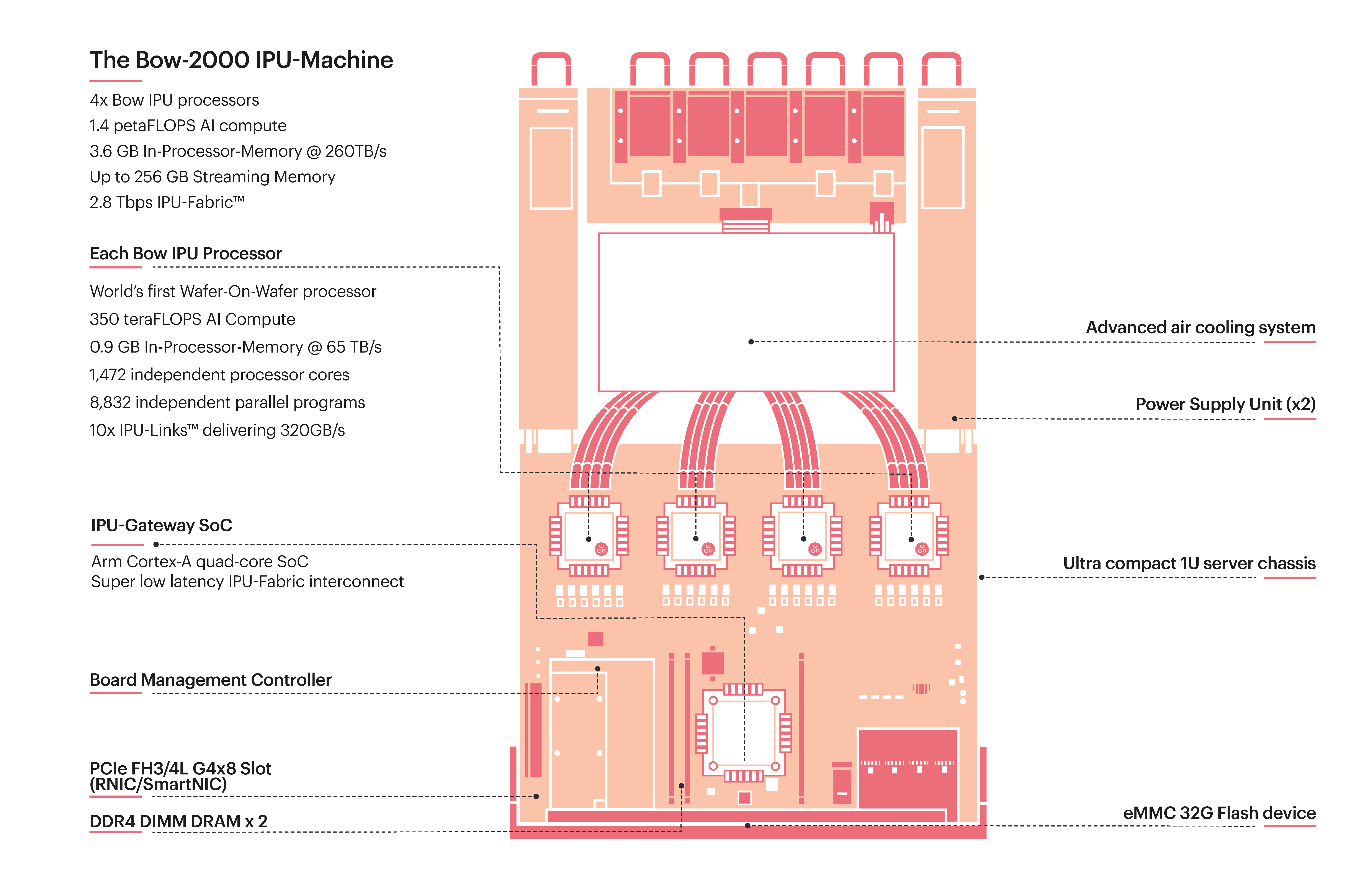
Fig. 2.1 Example of an IPU-Machine. The Bow-2000 is a building block for Bow Pod systems.
The IPU itself (Fig. 2.2) is made up of many independent processing units, called tiles (Section 2.3, Tile architecture). All the tiles are connected to an ultra-fast, all-to-all communication network called the exchange fabric. When multiple IPUs are connected together, the exchange fabric extends to all tiles on all of the IPUs.
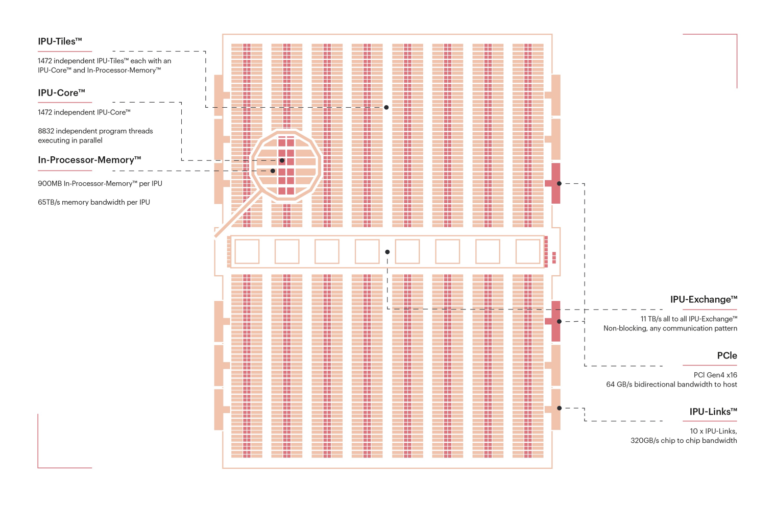
Fig. 2.2 IPU internal architecture
2.1. Memory architecture
The memory in an IPU-based machine is made up of In-Processor-Memory and Streaming Memory.
The In-Processor-Memory consists of the IPU’s local SRAM and is split into multiple disjoint memory units — one per tile — each of which has its own address space. The load/store instructions on a tile can only address the local memory on that tile. Code is also stored in the local tile memory and each tile will only execute code from its local memory.
The Streaming Memory is made up of several DDR memory chips. The tiles cannot execute load and store instructions to this memory directly.
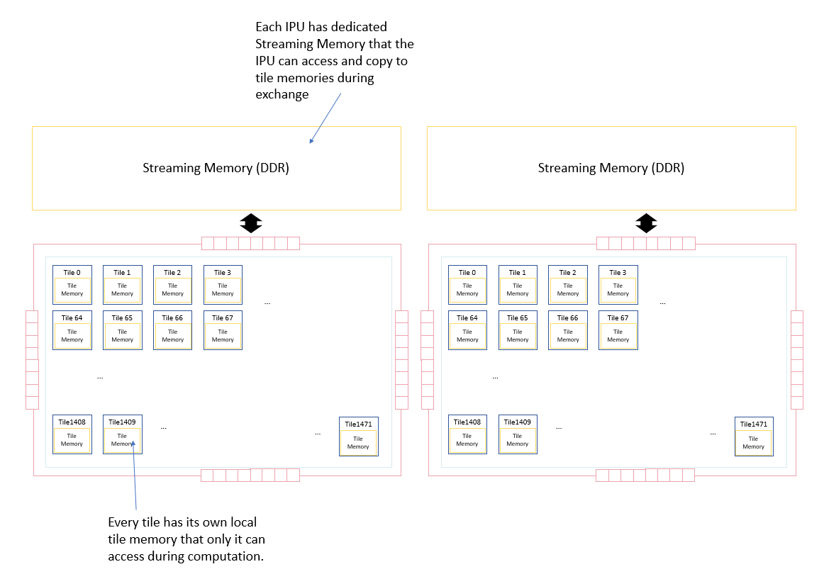
Fig. 2.3 IPU memory architecture
Data is moved between the memory on different tiles of the same IPU and between Streaming Memory and tile memory via explicit data movement instructions on the tiles which use the IPU’s exchange fabric. Before these instructions execute to perform the data movement, all the tiles must synchronise together. Synchronisation guarantees that all tiles have completed performing their compute tasks and are ready for data exchange.
2.2. Execution
When a program executes on an IPU, the tiles within the IPU alternate between exchanging data and performing compute on their local data.
The IPU uses the bulk-synchronous parallel (BSP) model of execution where the execution of a task is split into steps. Each step consists of the following phases:
local tile compute
global cross-tile synchronisation
data exchange
In the compute phase, all tiles execute in parallel, operating on their local data. After each tile finishes executing, it starts a synchronisation process to synchronise with the other tiles. When all tiles have reached this point, all the tiles will be synchronised and the IPU enters the exchange phase where data is copied between the tiles.
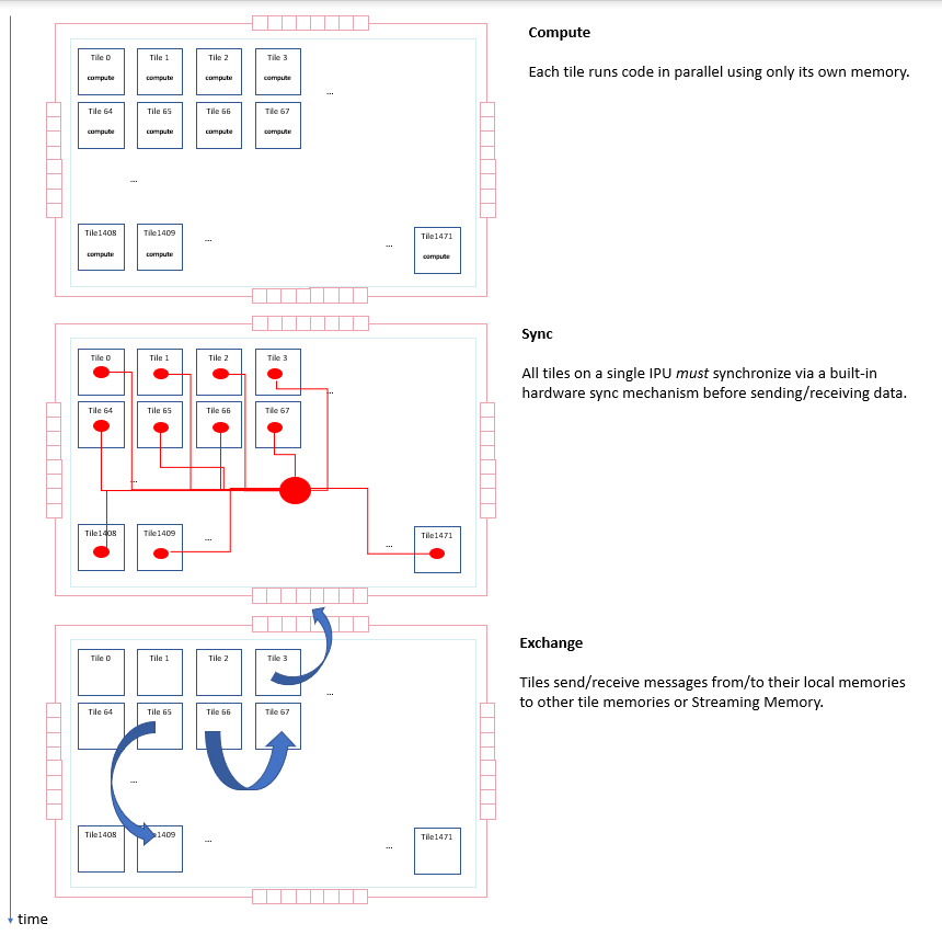
Fig. 2.4 Phases of task execution
After the exchange phase, the process repeats: the tiles move into a new compute phase, performing computation using their local data and the new data received during the exchange.
The program continues by executing a series of such steps, alternating between exchange and compute phases. Viewed as a timeline, we can see that each tile repeatedly performs the sequence of sync, exchange and compute, as shown in Fig. 2.5.
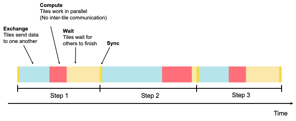
Fig. 2.5 Multiple phases in steps
Each step occurs in parallel across all tiles, but the whole IPU can be viewed as executing a sequence of steps in a serial fashion, each consisting of the sync, exchange and compute phases.
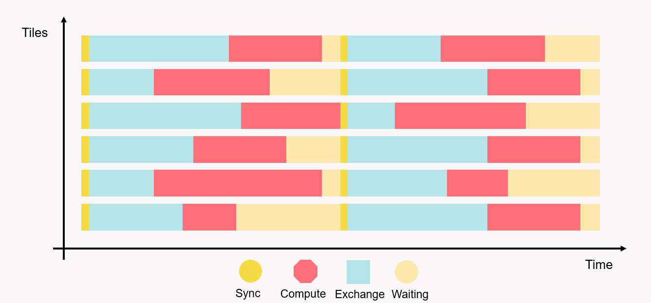
Fig. 2.6 Sync, exchange and compute activity across tiles
Fig. 2.6 shows a few tiles executing the steps. In the Popvision Graph Analyser we can see traces of activity across all 1472 tiles on an IPU for example in Fig. 2.7.
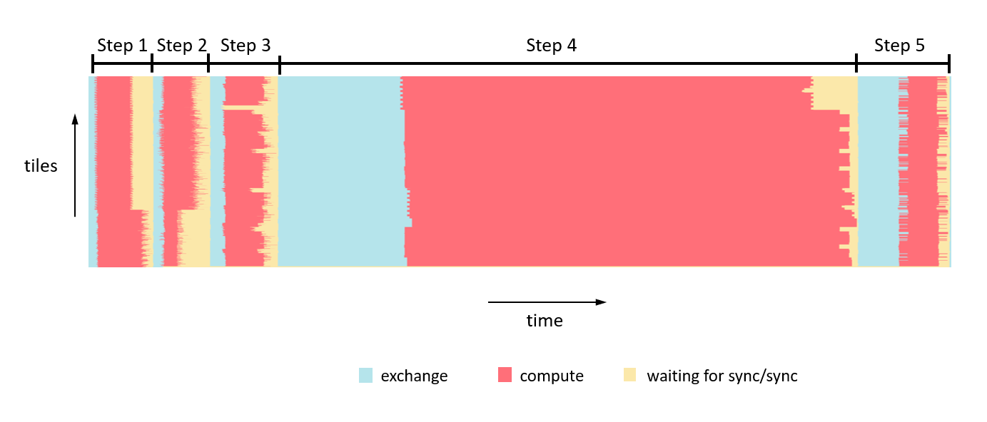
Fig. 2.7 Execution activity of all tiles in IPU
2.3. Tile architecture
Each tile consists of a single multi-threaded processor and its local memory.
The processor has two modes: supervisor and worker. At most one of the threads of the processor can run in supervisor mode and the thread running in supervisor mode can spawn other threads to run in worker mode. It is the supervisor thread that runs the top level control program for that tile. This thread implements the main program running over the set of IPUs executing an application. Section 3, Programming model contains details about the overall program model and how the supervisor programs combine to implement the main program running over a set of IPUs.
A task running on a worker thread will execute and when complete will exit — making the thread available for the supervisor to spawn a new task. It can happen that the supervisor spawns a task and all other threads are executing. In this case, the supervisor mode thread is suspended and is used for a worker task. The supervisor code will resume when a worker task completes and frees a thread.
The threads are executed by the processor in an instruction-by-instruction fixed order, each thread taking a turn in a “round-robin” fashion.
The processor instruction set used by the workers when executing tasks has been designed from scratch for machine learning and artificial intelligence. The instruction set contains:
Control flow instructions (jumps, conditionals, and so on) that can execute arbitrary control flow. The control flow on each processor is independent from those on the other processors.
Memory access instructions
Arithmetic instructions for integers and floating-point operations. The floating-point instructions are designed for high compute workloads and include single-precision (32 bit) and half-precision (16 bit) floating-point operations. The floating-point operations can be vectorised in small vectors of sizes 2, 4 and 8. In addition, there is an accumulating matrix product unit (the AMP unit) on each tile that can perform up to 64 multiply-accumulate operations per cycle.
Instructions to compute common transcendental functions (for example, the exponential function)
Instructions for random number generation. The random number generator is also connected to the floating-point unit to enable stochastic rounding in hardware when performing floating-point arithmetic.
Most worker instructions take one compute cycle to execute. This means that when the processor schedules that thread again, the next instruction can execute. Refer to the Tile Vertex Instruction Set Architecture for a list of the worker instructions that take more than one compute cycle to execute.
2.3.1. On-tile memory
Each tile on the IPU has on-tile memory. The details of the memory is dependent on the exact IPU.
For the GC200, each tile has 624 kilobytes of SRAM. This means that an IPU with 1,472 tiles has just under 900 MB of In-Processor-Memory in total.
Each tile uses a contiguous unsigned 21-bit address space, beginning at address 0x0. In practice, only a part of this memory space is populated with memory with the available memory starting at address 0x4C000 and ending at 0xE7FFF.
The memory is organised as two regions each made up of several 64-bit wide banks. Concurrent accesses can be made to different banks, while multiple accesses to the same bank must be sequential.
The banks in region 1 are interleaved, with bit 3 of the address selecting 64-bit words from alternating odd and even banks. Interleaving allows two 64-bit aligned addresses to be accessed simultaneously if they are an odd number of words apart. This means, for example, that an instruction can perform a 128-bit load as this reads the consecutive words from two different banks.
All loads and stores must be naturally aligned. Instructions can only be fetched from region 0.
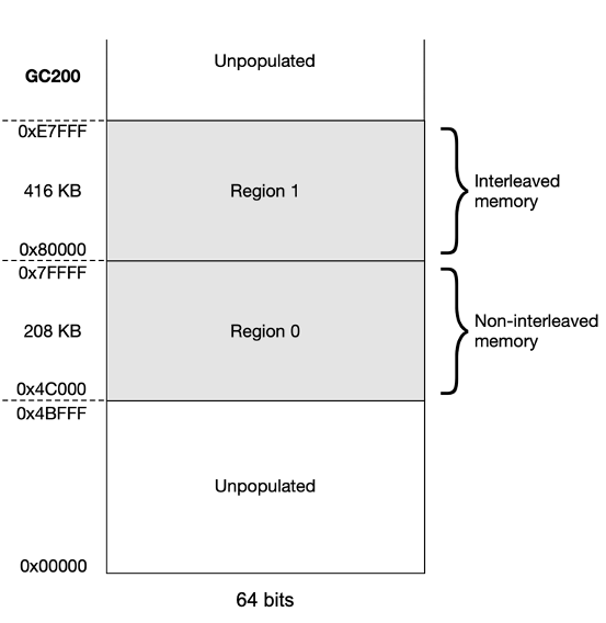
Fig. 2.8 IPU tile memory
For more details, refer to the Tile Vertex Instruction Set Architecture.
2.4. Host/device communication
IPUs can receive data from and send data to the memory of the host computer connected to the IPU.
On the IPU-Machine this is achieved via RDMA (remote direct memory access) over Ethernet. The RDMA NIC (network interface card) on the chassis containing the host computer will transfer data over Ethernet to an RDMA NIC on the IPU-Machine. On the IPU-Machine, the NIC will read data from and write data to DDR memory. The IPU will then read and write to that DDR memory during its exchange phase. The IPU will bridge the exchange messages to read packets from and write packets to the DDR memory. This communication architecture can be seen in Fig. 2.9.
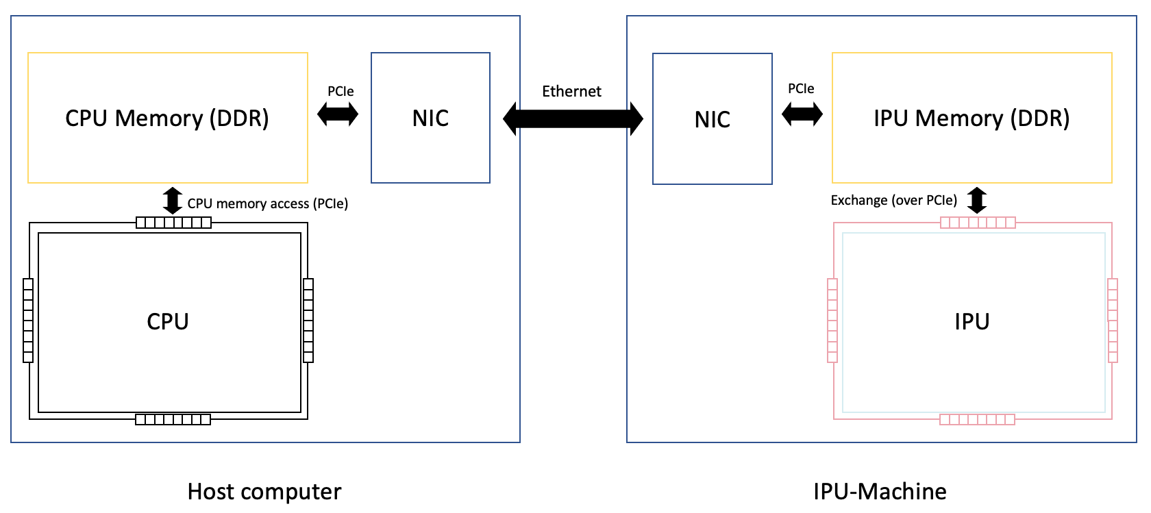
Fig. 2.9 Host to IPU communication