8. Networking
As the IPU-Machines in each IPU Pod are network appliances, network architecture and implementation are crucial to the correct function and performance of AI applications.
8.1. Requirements for reference design
Each vPOD must be completely isolated from any other vPOD. No shared networks except for the internet access network. This restriction also applies to the high-performance storage appliance which must be accessed via a dedicated VLAN, subnet and access interface for each vPOD. See Section 6, Storage for more information.
Poplar hosts (virtual or bare-metal) must have access to full-bandwidth RNICs without performance loss due to filtering, firewalls or other security measures.
100 GbE network infrastructure for the RDMA network must provide Priority Flow Control to support correct IPU-over-Fabric (IPUoF) operation.
IPU-Machine BMC and IPU-Gateway management ports must not be accessible from the Poplar hosts to increases the security of the IPU-Machines.
They are connected to the control instance of each vPOD as this is required for the vipu-server and for maintenance and administration.
As they are separated from the end-users they can share VLANs and subnets which allows for simple monitoring and management over a ‘back-end’ network.
An independent secure access path (for ssh) to vPOD control instances must be provided that doesn’t rely on the health of Poplar instances (which are externally accessible).
8.2. Physical connectivity
All 100 GbE connectivity to the Top of Rack (ToR) switch within each POD64 uses copper cabling by default, but using fibre and transceivers is also supported as an option.
All the 100 GbE connections from IPU Pod ToR switches to SPINE switches use optical cabling and Innolight transceivers (TR-ZC13H-N00 100G QSFP28 DR1 on the ToR switch end and T-OP4CNH-N00 OSFP DR4 on the SPINE switch end – connecting 4-to-1 cables).
There are two tested options for connecting the 1 GbE and 10 GbE management switches together across the racks:
A dedicated site core network. All management switches have uplinks to a separate core network for rack-rack traffic and for switch remote management.
Management switches are connected only to the 100 GbE switches in the same rack and VLANs are used to route management traffic over the shared 400 GbE SPINEs. This includes switch management traffic.
Whilst the second option reduces the physical connection complexity, it does make the management network dependent on the 400 GbE infrastructure meaning that a failure in the latter will impact the ability to even access switch and server management interfaces.
8.3. Openstack Overcloud networks
8.3.1. Control plane networks
There are 2 tested options for these networks:
They are configured in OpenStack by the Kayobe host config to use VLANs that reside on the 100 GbE physical infrastructure, and share this with application workloads. This provides greater throughput and reduced bottlenecks in the control nodes but increases the impact of any failures in that infrastructure.
They are configured to use VLANs solely on the physical management (1 GbE + 10 GbE) infrastructure. Whilst this increases isolation from workload data traffic, it has been shown to be vulnerable to the case where the control plan and control nodes are under heavy load. This can result in API protocol timeouts or other errors. An example would be when Cinder is copying disk images to hypervisors for VM launch.
8.3.2. Data plane networks
The data plane networks include any networks that are created inside tenant OpenStack projects. These include:
IPU RDMA traffic
Network storage traffic
Internet access
VM to VM management traffic, vPOD interactive logins
These networks are bound to the 100 GbE physical network in the Neutron ML2 configuration.
8.4. IP addressing and VLANs
The Graphcore standard global addressing policy for IPU Pods is used for the vPOD-local networks:
10.1.<logical rack number>.0/16: IPU-M BMC network shared by all vPODs.
10.2.<logical rack number>.0/16: IPU-M Gateway management shared by all vPODs.
10.3.<vPOD number>.0/24: vPOD-specific control network with an associated unique VLAN.
10.5.<vPOD number>.0/16: vPOD-specific IPU data RDMA network with an associated unique VLAN.
The logical rack number denotes the physical install location of the POD64 containing the IPU-Machines and the vPOD number is a unique number given to each vPOD.
Note
Multiple vPODs may use IPU-Machines from a single logical rack. In this case, the logical rack number will be common but the vPOD number will be distinct.
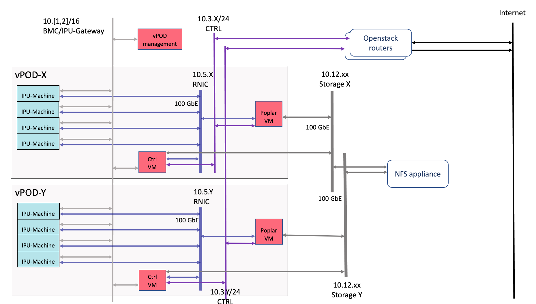
Fig. 8.1 Logical network view of vPODs
In addition, each vPOD may use this convention for a storage network:
10.12.<vPOD number>.0/24: 100 GbE storage network where a unique number is allocated to the vPOD and a unique VLAN is associated with this subnet.
DHCP is provided by Openstack Neutron and used for all vPOD interfaces including those on the IPU-Machines. This requires a configuration to be populated with MAC addresses for all IPU-Machine interfaces (BMC, IPU-Gateway and RNIC) to ensure IPs are assigned in standard order. For example, IPU-Machine #12 in logical rack 25 will be assigned:
10.1.25.12 for BMC
10.2.25.12 for IPU-Gateway
10.5.25.12 for RNIC
Addresses for interfaces on virtual machines are not constrained in this way and are allocated randomly from a DHCP pool by Neutron.
Warning
DNS within vPODs
Due to the number of networks connected to some VMs, there may be issues with DNS. Some OS clients have a limit on the number of listed DNS servers which can lead to an inability to resolve.
To avoid this issue, each VM is configured to only resolve via the 10.3 control network. This provides a relevant address for control and Poplar instances but not for IPU-Machines. Consequently these must be addressed by IP when creating VIPU agents or other admin tasks.
8.5. Traffic control
For correct IPUoF operation and performance, the 100 GbE network must implement Priority Flow Control but not any other negotiated traffic policies.
8.6. 100 GbE networks with RDMA over Converged Ethernet (RoCE)
This is implemented with a vPOD-specific VLAN directly on the network switches for each vPOD.
All VMs are configured with direct mode Neutron ports when connecting to the IPU RDMA network. This allows for the required RDMA protocols to be used to the IPU-Machines.
Note
Each Mellanox card has a fixed number of Virtual Functions (VFs) available which limits the number of virtual machines which can be connected using direct mode on a single server or hypervisor.
The use of direct mode prevents the application of security groups (on current network cards) so access to the VLAN must be restricted explicitly by the infrastructure.
Neutron direct mode can also used for storage networks to obtain maximum performance.
8.7. Link aggregation
8.7.1. IPU Pod ToR switches
All connections from ToR 100 GbE switches use 8x 100 GbE links with 2x 4-way LAG to a pair of redundant 400 GbE SPINE switches.
Arista switches support active/active configurations providing up to 800 Gb/s of bandwidth and 400 Gb/s in fall-back mode in the case of a failures.
8.7.2. Poplar servers
For both Poplar bare-metal servers and where Poplar servers are used as hypervisors, a 2-way LAG is used to bond the pair of 100 GbE RNICs on each server giving up to 200 Gb/s aggregate throughput.
For hypervisors this bonded interface then carries all the VLANs associated with both the hypervisor (Overcloud networks) and the virtual machines (IPU and storage networks). See Section 5.3, Neutron (Open vSwitch) for more details.
8.8. Mellanox Connect-X 5
This network card is used in all physical Poplar servers, Ceph nodes and control nodes.
8.8.1. Virtual function passthrough
The Mellanox driver is modified to allow the maximum number of bonded-VF to be used (set 64 per card, default is 16).
See Section 5.3, Neutron (Open vSwitch) for related information.
8.9. vPOD logical networks
8.9.1. Security groups
The following traffic restrictions are enforced for VMs on the networks in a vPOD. This is configured in OpenStack Neutron.
Protocol |
Port |
Source/Destination |
Reason |
|---|---|---|---|
vPOD Controller VM interface in IPU-Machine BMC network |
|||
Egress |
|||
ICMP |
IPU-Machine BMC addresses |
Check connectivity |
|
TCP |
22 (ssh) |
IPU-Machine BMC addresses |
Remote access to shell |
TCP |
443 (https) |
TBC |
TBC |
TCP, UDP |
53 (dns) |
DNS agent provided by Neutron |
|
Ingress |
|||
UDP |
514 |
IPU-Machine BMC addresses |
Collect incoming logs from all IPU-Machine BMC |
vPOD Controller VM interface in IPU-Machine IPU-Gateway network |
|||
Egress |
|||
ICMP |
Any |
Check connectivity |
|
TCP |
22 (ssh) |
IPU-Machine IPU-Gateway addresses |
Remote access to shell |
TCP |
2112 |
IPU-Machine IPU-Gateway addresses |
Collect metrics from Prometheus exporter |
TCP |
8080 |
IPU-Machine IPU-Gateway addresses |
Manage hardware using V-IPU agent (VIRM) from V-IPU server |
TCP, UDP |
53 |
DNS agent provided by Neutron |
|
Ingress |
|||
TCP |
22 |
Global management server |
For remote administration |
TCP |
2113 |
Global management server |
Expose metrics by Prometheus exporter |
TCP |
3000 |
Global management server |
Expose Grafana |
TCP |
9090 |
Global management server |
Expose Prometheus for federation |
UDP |
514 |
IPU-Machine IPU-Gateway addresses |
Collect incoming logs from all IPU-Machine IPU-Gateways |
vPOD Controller VM interface in vPOD management network |
|||
Egress |
|||
Any |
Any |
Any |
Egress to any allowed |
Ingress |
|||
TCP |
22 |
Any |
Remote access to shell |
TCP |
8090 |
Poplar VMs |
Access for Poplar VMs to V-IPU server |
Poplar VM interface in vPOD management network |
|||
Egress |
|||
Any |
Any |
Any |
Egress to any allowed |
Ingress |
|||
TCP |
22 |
Any |
Remote access to shell |
TCP |
9100 |
V-IPU Controller |
Expose node exporter for Prometheus |
Poplar VM in IPU data network |
|||
No filtering possible: DIRECT NIC without security groups |
|||
Poplar VM in storage network (examples only for NFS) |
|||
Egress |
|||
TCP, UDP |
NFS |
NFS server |
Allow access to NFS storage server |
No ingress |
|||