3. Physical installation
3.1. Graphcore IPU Pod installation
All the IPU Pods in this reference design are physically built as standard IPU-Machine (IPU-M2000 or Bow-2000) IPU Pod64 configurations as described in the IPU-POD64 Reference Design: Build and Test Guide and Bow Pod64 Reference Design: Build and Test Guide, respectively.
Note that the following may be subject to change in subsequent revisions of the build and test guides:
4x R6525 AMD servers are used with 512 GB RAM each. The RAM is installed with 8x DIMM modules to provide 8 symmetrical NUMA nodes.
Both 100 Gb RNIC ports on each Poplar server are connected to the ToR switch.
Both management network ports on each IPU-Machine are connected to the management switch although only one management network port is currently used. This port is shared by the BMC and IPU-Gateway virtual interfaces via a micro-switch built into the IPU-Machine. The IPU-Machine firmware includes an option to split this to use the separate interfaces, but this has not been tested for this design.
Each R6525 server is configured to PXE boot from a 1 Gb (or 10 Gb) interface. The physical connection is described in the relevant build and test guide. There are several 1 Gb interfaces on these hosts and the network cards vary so the logical interface can appear differently to the OS.
Dell iDRAC settings:
Firmware upgrades:
BIOS: 3.9.3
iDRAC: 6.10.00.00
Mellanox ConnectX-5: 16.26.1040
Hyperthreading is enabled
NUMA per socket (NPS) = 4
Optimised PCIe settings:
PCIe preferred I/O bus: enabled
PCIe preferred I/O bus value: 161 (PCIe slot that contains the RNIC card)
RAID for boot and OS drives
IDRAC service account for Kayobe connection, and IPMI enabled:
Role: adminstrator
IPMI LAN privilege: adminstrator
Tuned for maximum performance:
CPU power management: maximum performance
Turbo boost: enabled
C states: disabled
The MAC addresses of all the IPU-Machine interfaces need to be gathered as part of the installation to allow for DHCP to be configured. The 1 GbE interface MACs are listed on labels but the RNIC interface MACs can only be found after network access has been setup. This means that there are several options for the first install:
Connect the IPU-Machines to the 100 GbE ToR switch and power them on. The MAC addresses can then be seen by the switch and gathered from the switch management interface.
Install and configure as a standalone bare-metal IPU Pod with factory IP addressing (as per the build and test guides) then query the RNIC MAC addresses. You can then redeploy the IPU Pod under the Openstack Ironic automation. You can also perform hardware tests on the IPU-Machines at this stage.
Deploy the IPU Pod with Ironic and Neutron OpenStack projects using the 1 GbE interface MACs gathered from labels, but without the RNIC information. After deployment gather the RNIC interfaces and update the DHCP configuration and re-deploy.
3.2. Infrastructure hosts
3.2.1. Ceph nodes (x5)
For the reference design these are Dell R640 Intel 96 core servers with 768 GB RAM, 2x 100 GbE, 7x 1 TB NVME, 2x 500 GB SSD (as hardware RAID1).
Each server should provide >= 7 TB of NVME storage using multiple devices since this is better for Ceph OSDs.
These nodes also operate as Hypervisors for general compute purposes.
Section 6.2, Ceph clusters provides more details.
3.2.2. OpenStack control nodes (x3)
For the reference design these are Dell R640 Intel 96 core servers with 768 GB RAM, 2x 100 GbE, 7x 1 TB NVME, 2x 500 GB SSD (as hardware RAID1). These may be over-specified in terms of memory and CPU for your system.
These nodes run the OpenStack Overcloud core control services (as bare-metal containers).
Three servers are needed to provide HA.
3.2.3. Seed and Ansible control nodes (x2)
You will require servers with a minimum of:
8 core CPU
12 GB memory
100 GB free disk space (partitioned if possible to separate the Docker volume storage from the host OS)
1x 1 Gb Ethernet
In the reference design the servers are Dell PowerEdge R440 with Xeon Silver 4210 2.2 GB CPU, 128 GB RAM, Dual 25 GbE Ethernet, 2x 480 GB SATA SSD.
Note
Only one server is required for a single cloud installation. In our example two were used to allow for an independent development setup.
This host runs a pre-built seed VM in which OpenStack docker containers are run to manage the OpenStack cloud. This is also referred to as the Undercloud. This host must have access to power management and provisioning/control networks for the remote servers to be provisioned into the OpenStack cloud.
3.3. Core networking
3.3.1. Multi-rack interconnect
The Pod64 racks (described in Section 3.1, Graphcore IPU Pod installation) and the OpenStack infrastructure racks have 8x 100 GbE uplinks to a shared 400 GbE spine. Ideally this would be connected as 4x 100 GbE to each of a pair of MLAG 400 GbE switches to provide redundant connectivity with a minimum 400 GbE throughput. Fig. 3.1 shows a general network architecture for multi-rack connectivity. This includes options for storage, disaggregated compute and other services including the OpenStack infrastructure.
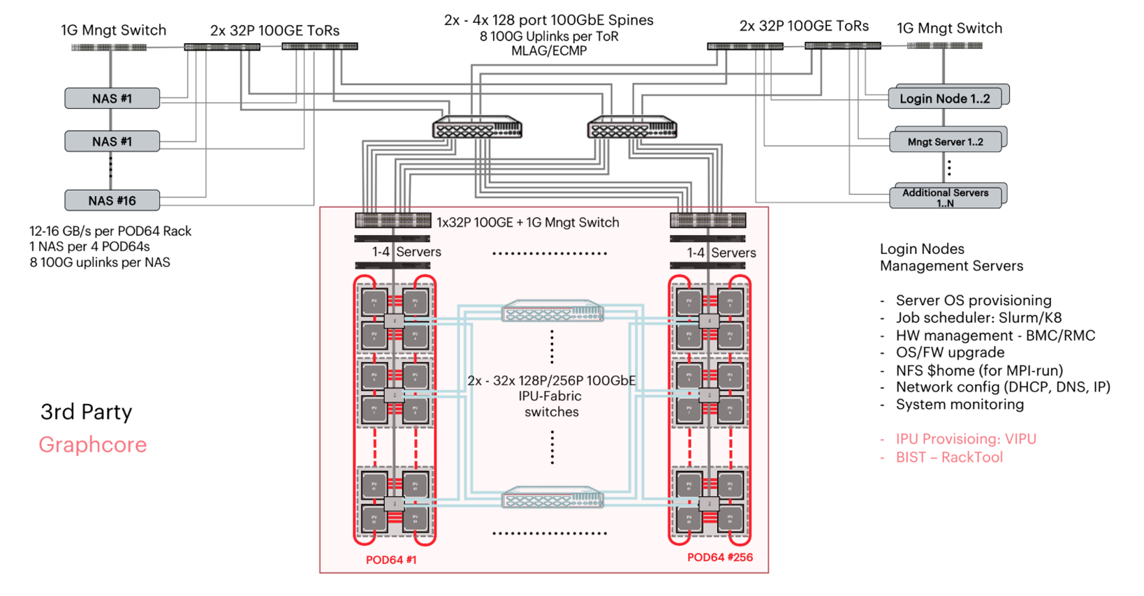
Fig. 3.1 Multi-rack connectivity
3.4. Power and cooling
Each Pod64 rack requires power at:
1500 W per IPU-M2000 (1700 W for Bow-2000)
1400 W per Poplar host
333 W (max) for Arista 7060 switch
52 W (max) for Arista 7010T switch
3.5. Network components
This section describes networks, endpoints, physical devices and the relationships between them.
3.5.1. 1 GbE management network
This network has the following devices and services connected:
Poplar servers: 2x 1 GbE interfaces and IPMI interface
Infrastructure servers: 2x 1 GbE interfaces and IPMI interface
IPU-Machines: will have either
A single connection to the 1 GbE presenting two MAC addresses, one for IPU BMC and one for the IPU-Gateway; or
Two 1 GbE connections, one for BMC and one for the IPU-Gateway (untested in this reference architecture)
PDUs in each rack: management interface
100 GbE switch: management interface
The purpose of this network is to provide connections for managing devices.
3.5.2. 100 GbE data network
This network has the following devices and services connected:
Poplar servers (Hypervisors): 2x RNIC 100 GbE interfaces (configured as a bonded MLAG pair)
IPU-Machines: 100 GbE interfaces
OpenStack control plane with virtual networks plus block, object and file storage
High performance 3rd party storage (optional)
3.5.3. Networks and VLANs
The physical switches (1 GbE management switch and 100 GbE data switch) provide physical network access to the IPU-Machines, infrastructure hosts and Poplar servers. To separate data and management traffic, and to separate the various tenants, VLANs are added as provider networks within OpenStack Neutron. Neutron will then provide IPAM and DHCP for these provider networks, along with any required routing.
A typical VLAN set would be:
Overcloud networks
Provisioning networks (for deploying and managing host OS )
Out-of-band management network (for IPMI power management)
‘Internal’ network for OpenStack control plane communication
‘Tunnel’ network for VXLAN tunnels between Open vSwitch instances
‘Storage’ network for Ceph connectivity
Additional networks for other OpenStack services if enabled, for example:
Octavia (LBaaS)
Manila (NFSaaS)
Public storage (if exposing Ceph to user workloads)
External network (for exposing workloads)
External high-performance storage
VLAN range for VLAN based provider networks to be used in user tenancies